
|
|
Forum Index : Microcontroller and PC projects : MM2: 3.2" Colour TFT Touchscreen
| Author | Message | ||||
| WhiteWizzard Guru Joined: 05/04/2013 Location: United KingdomPosts: 2794 |
Grogs, Are you planning on using the two 8-bit shift registers too? (as hinted by Peter) One thing worth including is pwm backlight control . . . For everything Micromite visit micromite.org Direct Email: whitewizzard@micromite.o |
||||
| matherp Guru Joined: 11/12/2012 Location: United KingdomPosts: 8604 |
Grogster Suggest you hold off designing a board for a few days - I might have something interesting to suggest soon 
P |
||||
| WhiteWizzard Guru Joined: 05/04/2013 Location: United KingdomPosts: 2794 |
110"  For everything Micromite visit micromite.org Direct Email: whitewizzard@micromite.o |
||||
Grogster Admin Group Joined: 31/12/2012 Location: New ZealandPosts: 9082 |
Owwwwwww - peaked my interest. I will hold off till you impress us all again.  Smoke makes things work. When the smoke gets out, it stops! |
||||
bigmik Guru Joined: 20/06/2011 Location: AustraliaPosts: 2870 |
I am starting not to like you anymore MatherP, 
I have been buying up all this displays and now you changed you mind.. 
All in jest of course... Keep up the fantastic work, I feel because of your efforts we are onto something fantastic here. Regards, Mick Mick's uMite Stuff can be found >>> HERE (Kindly hosted by Dontronics) <<< |
||||
| Grogster Admin Group Joined: 31/12/2012 Location: New ZealandPosts: 9082 |
He may well be using the display - why re-invent the wheel? It's just he might be designing his own carrier board in the same way I was thinking of doing. We'll wait in suspense!!! Smoke makes things work. When the smoke gets out, it stops! |
||||
Oldbitcollector Senior Member Joined: 16/05/2014 Location: United StatesPosts: 172 |
@matherp First of all, thank you for all your efforts on this. I bought one of these displays thinking that it might be compatible. Upon actual inspection, I'm having trouble lining up the I/O with what appears in your code. Does this display appear to be compatible with what you have been working with there? (BTW, these screens are TINY.) Thanks jeff My Propeller/Micromite mini-computer project. |
||||
| Grogster Admin Group Joined: 31/12/2012 Location: New ZealandPosts: 9082 |
Driver for that display is ILI9341. Is that supported? Not sure... If not, then probably not. Smoke makes things work. When the smoke gets out, it stops! |
||||
| Oldbitcollector Senior Member Joined: 16/05/2014 Location: United StatesPosts: 172 |
My mistake! It should have been posted to his other thread.. http://www.thebackshed.com/forum/forum_posts.asp?TID=7358&PN =1 I'll leave it be for now and see if he reports in. There is indications that his code does support the chip, I'm just not sure about the interface itself. thanks Jeff My Propeller/Micromite mini-computer project. |
||||
TassyJim Guru Joined: 07/08/2011 Location: AustraliaPosts: 5923 |
You should try the three main chips just in case the advert is not right about which one it uses. Don't worry about the size until you 'see the light' The pins for RST, CE and CD(or D/C) are set as constants in the software. SPI clock (pin 25) goes to CLK and SPI OUT (pin 3) goes to DIN. For the S6D02A1 chips, I modified Peter's code: 2015-01-30_052926_TFT-S6D02A1-SPI.zip Jim VK7JH MMedit MMBasic Help |
||||
| matherp Guru Joined: 11/12/2012 Location: United KingdomPosts: 8604 |
I've got to the point where I think it is about safe (i.e it should probably end up working!) to reveal what I have been up to 
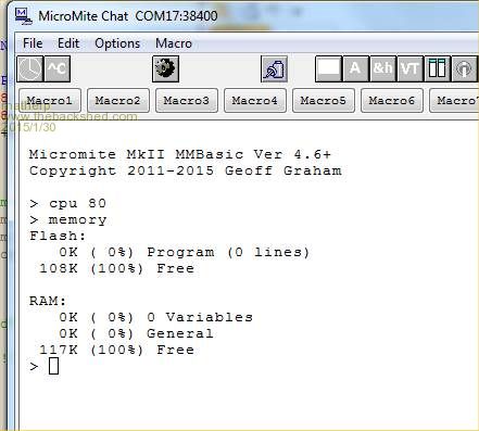
With Geoff's help and agreement I've been porting the Micromite firmware to the PIC32MX470F512 chips - why? Twice the flash memory and RAM - see the picture Twice the speed, Currently the maximum is 80Mhz but 96 should be possible if I can sort out some sort of configuration issue. A full 16-bit data port completely separate from all of the special purpose pins - perfect for driving TFT displays even faster! The PIC32MX470F512 is available in 2 packages that are useful to us, a 64-pin TQFP and a 100-pin TQFP, the same firmware will support both but it is different from the 28 and 44-pin versions. The 64-pin chip is probably the perfect version for us. I've mounted the 100-pin version on a spare Colour Maximite PCB as a test-bed. A mono-Maximite PCB or mini-Maximite would be an ideal test-bed for the 64-pin chip. If anyone has a spare of these lying around (or anything else suitable) they would be willing to let me have please PM me. The pinouts of the 470 chips are exactly the same as the PIC32MX695 chips used in the Maximites but for the avoidance of doubt the 695 chips are much less similar to the 170s and I will not be porting to them! 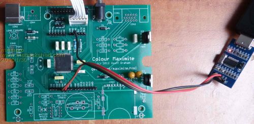
Once I've done more testing myself I will be asking for volunteers to beta-test the code and if all goes well I'm hoping Geoff will take it over as part of the official Micromite release - hopefully he won't find my code too terrible. Obviously, the relevance of this to this thread is that the 64-pin version would make the perfect CPU for a display backpack. The starting point though should probably be a DIL breakout like the ones that have been made for the 44-pin chip. I've attached the pin-out details for the chips ( equivalent to pages 6 and 7 in the Micromite manual) for information. The current status is that the chip is up and running as evidenced above. I can load and run programs (including Cfunctions) through MMEDIT and use local edit as normal. The increased CPU speed is definitely effective (6msec for my sort code vs 11 before). I can address all the I/O pins but I haven't yet tested any functionally. 64-Pin Micromite Pin 1-PortE5:ANALOG_IN22 | DIGITAL_IN | DIGITAL_OUT Pin 2-PortE6 ANALOG_IN23 | DIGITAL_IN | DIGITAL_OUT Pin 3-PortE7 ANALOG_IN27 | DIGITAL_IN | DIGITAL_OUT Pin 4-PortG6 ANALOG_IN16 | DIGITAL_IN | DIGITAL_OUT | PWM Pin 5-PortG7 ANALOG_IN17 | DIGITAL_IN | DIGITAL_OUT Pin 6-PortG8 ANALOG_IN18 | DIGITAL_IN | DIGITAL_OUT | COUNT Pin 7-RESET/MCLR Pin 8-PortG9 ANALOG_IN19 | DIGITAL_IN | DIGITAL_OUT | Comm1 Enable Pin 9-GROUND Pin 10-POWER (+2.3 to +3.6V) Pin 11-PortB5 ANALOG_IN5 | DIGITAL_IN | DIGITAL_OUT Pin 12-PortB4 ANALOG_IN4 | DIGITAL_IN | DIGITAL_OUT Pin 13-PortB3 ANALOG_IN3 | DIGITAL_IN | DIGITAL_OUT Pin 14-PortB2 ANALOG_IN2 | DIGITAL_IN | DIGITAL_OUT Pin 15-PortB1 ANALOG_IN1 | DIGITAL_IN | DIGITAL_OUT | PGEC1 Pin 16-PortB0 ANALOG_IN0 | DIGITAL_IN | DIGITAL_OUT | PGED1 Pin 17-PortB6 ANALOG_IN6 | DIGITAL_IN | DIGITAL_OUT Pin 18-PortB7 ANALOG_IN7 | DIGITAL_IN | DIGITAL_OUT Pin 19-ANALOG REFERENCE Pin 20-ANALOG GROUND Pin 21-PortB8 ANALOG_IN8 | DIGITAL_IN | DIGITAL_OUT Pin 22-PortB9 ANALOG_IN9 | DIGITAL_IN | DIGITAL_OUT Pin 23-PortB10 ANALOG_IN10 | DIGITAL_IN | DIGITAL_OUT Pin 24-PortB11 ANALOG_IN11 | DIGITAL_IN | DIGITAL_OUT Pin 25-GROUND Pin 26-POWER (+2.3 to +3.6V) Pin 27-PortB12 ANALOG_IN12 | DIGITAL_IN | DIGITAL_OUT Pin 28-PortB13 ANALOG_IN13 | DIGITAL_IN | DIGITAL_OUT Pin 29-PortB14 ANALOG_IN14 | DIGITAL_IN | DIGITAL_OUT Pin 30-PortB15 ANALOG_IN15 | DIGITAL_IN | DIGITAL_OUT Pin 31-PortF4 DIGITAL_IN | DIGITAL_OUT | 5V | Comm1 RX Pin 32-PortF5 DIGITAL_IN | DIGITAL_OUT | 5V | Comm1 TX Pin 33-PortF3 DIGITAL_IN | INTERRUPT | DIGITAL_OUT | 5V Pin 34-UNUSED | VBUS Pin 35-POWER (+2.3 to +3.6V) | USSB3V3 Pin 36-UNUSED | USBD- Pin 37-UNUSED | USBD+ Pin 38-POWER (+2.3 to +3.6V) Pin 39-PortC12 DIGITAL_IN | INTERRUPT | DIGITAL_OUT Pin 40-PortC15 DIGITAL_IN | INTERRUPT | DIGITAL_OUT Pin 41-GROUND Pin 42-PortD8 DIGITAL_IN | DIGITAL_OUT | 5V | PWM Pin 43-PortD9 DIGITAL_IN | DIGITAL_OUT | 5V | I2CSDA Pin 44-PortD10 DIGITAL_IN | DIGITAL_OUT | 5V | I2CSCL Pin 45-PortD11 DIGITAL_IN | DIGITAL_OUT | 5V | SPIIN Pin 46-PortD0 DIGITAL_IN | DIGITAL_OUT | 5V | WAKEUP/IR Pin 47-PortC13 DIGITAL_IN | DIGITAL_OUT | PWM Pin 48-PortC14 DIGITAL_IN | DIGITAL_OUT | PWM Pin 49-PortD1 ANALOG_IN24 | DIGITAL_IN | DIGITAL_OUT | COUNT Pin 50-PortD2 ANALOG_IN25 | DIGITAL_IN | DIGITAL_OUT | SPICLK Pin 51-PortD3 ANALOG_IN26 | DIGITAL_IN | DIGITAL_OUT | COUNT Pin 52-PortD4 DIGITAL_IN | DIGITAL_OUT | 5V | COUNT Pin 53-PortD5 DIGITAL_IN | DIGITAL_OUT | 5V | PWM Pin 54-PortD6 DIGITAL_IN | INTERRUPT | DIGITAL_OUT | 5V Pin 55-PortD7 DIGITAL_IN | INTERRUPT | DIGITAL_OUT | 5V Pin 56-VCAP:47uF TANT CAPACITOR, 10|47uF Multilayer ceramic Pin 57-POWER (+2.3 to +3.6V) Pin 58-Console TX Pin 59-Console RX Pin 60-PortE0 DIGITAL_IN | INTERRUPT | DIGITAL_OUT | 5V Pin 61-PortE1 DIGITAL_IN | INTERRUPT | DIGITAL_OUT | 5V Pin 62-PortE2 ANALOG_IN20 | DIGITAL_IN | DIGITAL_OUT | Comm2 TX Pin 63-PortE3 DIGITAL_IN | INTERRUPT | DIGITAL_OUT | 5V | Comm2 RX Pin 64-PortE4 ANALOG_IN21 | DIGITAL_IN | DIGITAL_OUT 100-Pin Micromite Pin 1-PortG15 DIGITAL_IN | DIGITAL_OUT | 5V Pin 2-POWER (+2.3 to +3.6V) Pin 3-PortE5 ANALOG_IN22 | DIGITAL_IN | DIGITAL_OUT Pin 4-PortE6 ANALOG_IN23 | DIGITAL_IN | DIGITAL_OUT Pin 5-PortE7 ANALOG_IN27 | DIGITAL_IN | DIGITAL_OUT Pin 6-PortC1 DIGITAL_IN | DIGITAL_OUT | 5V Pin 7-PortC2 DIGITAL_IN | DIGITAL_OUT | 5V Pin 8-PortC3 DIGITAL_IN | DIGITAL_OUT | 5V Pin 9-PortC4 DIGITAL_IN | DIGITAL_OUT | 5V Pin 10-PortG6 ANALOG_IN16 | DIGITAL_IN | DIGITAL_OUT | PWM Pin 11-PortG7 ANALOG_IN17 | DIGITAL_IN | DIGITAL_OUT | SPIOUT Pin 12-PortG8 ANALOG_IN18 | DIGITAL_IN | DIGITAL_OUT | COUNT Pin 13-RESET/MCLR Pin 14-PortG9 ANALOG_IN19 | DIGITAL_IN | DIGITAL_OUT | Comm1 Enable Pin 15-GROUND Pin 16-POWER (+2.3 to +3.6V) Pin 17-PortA0 DIGITAL_IN | DIGITAL_OUT | 5V Pin 18-PortE8 DIGITAL_IN | DIGITAL_OUT | 5V Pin 19-PortE9 DIGITAL_IN | DIGITAL_OUT | 5V Pin 20-PortB5 ANALOG_IN5 | DIGITAL_IN | DIGITAL_OUT Pin 21-PortB4 ANALOG_IN4 | DIGITAL_IN | DIGITAL_OUT Pin 22-PortB3 ANALOG_IN3 | DIGITAL_IN | DIGITAL_OUT Pin 23-PortB2 ANALOG_IN2 | DIGITAL_IN | DIGITAL_OUT Pin 24-PortB1 ANALOG_IN1 | DIGITAL_IN | DIGITAL_OUT Pin 25-PortB0 ANALOG_IN0 | DIGITAL_IN | DIGITAL_OUT Pin 26-PortB6 ANALOG_IN6 | DIGITAL_IN | DIGITAL_OUT | PGEC2 Pin 27-PortB7 ANALOG_IN7 | DIGITAL_IN | DIGITAL_OUT | PGED2 Pin 28-PortA9 DIGITAL_IN | DIGITAL_OUT Pin 29-PortA10 DIGITAL_IN | DIGITAL_OUT Pin 30-ANALOG REFERENCE Pin 31-ANALOG GROUND Pin 32-PortB8 ANALOG_IN8 | DIGITAL_IN | DIGITAL_OUT Pin 33-PortB9 ANALOG_IN9 | DIGITAL_IN | DIGITAL_OUT Pin 34-PortB10 ANALOG_IN10 | DIGITAL_IN | DIGITAL_OUT Pin 35-PortA11 ANALOG_IN11 | DIGITAL_IN | DIGITAL_OUT Pin 36-GROUND Pin 37-POWER (+2.3 to +3.6V) Pin 38-PortA1 DIGITAL_IN | DIGITAL_OUT | 5V Pin 39-PortF13 DIGITAL_IN | DIGITAL_OUT | 5V Pin 40-PortF12 DIGITAL_IN | DIGITAL_OUT | 5V Pin 41-PortB12 ANALOG_IN12 | DIGITAL_IN | DIGITAL_OUT Pin 42-PortB13 ANALOG_IN13 | DIGITAL_IN | DIGITAL_OUT Pin 43-PortB14 ANALOG_IN14 | DIGITAL_IN | DIGITAL_OUT Pin 44-PortB15 ANALOG_IN15 | DIGITAL_IN | DIGITAL_OUT Pin 45-GROUND Pin 46-POWER (+2.3 to +3.6V) Pin 47-PortD14 DIGITAL_IN | DIGITAL_OUT | 5V Pin 48-PortD15 DIGITAL_IN | DIGITAL_OUT | 5V Pin 49-PortF4 DIGITAL_IN | DIGITAL_OUT | 5V | Comm1 RX Pin 50-PortF5 DIGITAL_IN | DIGITAL_OUT | 5V | Comm1 TX Pin 51-PortF3 DIGITAL_IN | DIGITAL_OUT | 5V Pin 52-PortF2 DIGITAL_IN | DIGITAL_OUT | 5V Pin 53-PortF8 DIGITAL_IN | DIGITAL_OUT | 5V Pin 54-VBUS Pin 55-POWER (+2.3 to +3.6V) | VUSB3V3 Pin 56-D- Pin 57-D+ Pin 58-PortA2 DIGITAL_IN | DIGITAL_OUT | 5V Pin 59-PortA3 DIGITAL_IN | DIGITAL_OUT | 5V Pin 60-PortA4 DIGITAL_IN | DIGITAL_OUT | 5V Pin 61-PortA5 DIGITAL_IN | DIGITAL_OUT | 5V Pin 62-POWER (+2.3 to +3.6V) Pin 63-PortC12 DIGITAL_IN | INTERRUPT | DIGITAL_OUT Pin 64-PortC15 DIGITAL_IN | INTERRUPT | DIGITAL_OUT Pin 65-GROUND Pin 66-PortA14 DIGITAL_IN | DIGITAL_OUT | 5V | I2CSCL Pin 67-PortA15 DIGITAL_IN | DIGITAL_OUT | 5V | I2CSDA Pin 68-PortD8 DIGITAL_IN | DIGITAL_OUT | 5V | PWM Pin 69-PortD9 DIGITAL_IN | DIGITAL_OUT | 5V Pin 70-PortD10 DIGITAL_IN | DIGITAL_OUT | 5V | SPICLK Pin 71-PortD11 DIGITAL_IN | DIGITAL_OUT | 5V | SPIIN Pin 72-PortD0 DIGITAL_IN | DIGITAL_OUT | 5V | WAKEUP/IR Pin 73-PortC13 DIGITAL_IN | DIGITAL_OUT | PWM Pin 74-PortC14 DIGITAL_IN | DIGITAL_OUT | PWM Pin 75-GROUND Pin 76-PortD1 ANALOG_IN24 | DIGITAL_IN | DIGITAL_OUT | COUNT Pin 77-PortD2 ANALOG_IN25 | DIGITAL_IN | DIGITAL_OUT Pin 78-PortD3 ANALOG_IN26 | DIGITAL_IN | DIGITAL_OUT | COUNT Pin 79-PortD12 DIGITAL_IN | DIGITAL_OUT | 5V Pin 80-PortD13 DIGITAL_IN | DIGITAL_OUT | 5V Pin 81-PortD4 DIGITAL_IN | DIGITAL_OUT | 5V | COUNT Pin 82-PortD5 DIGITAL_IN | DIGITAL_OUT | 5V | PWM Pin 83-PortD6 DIGITAL_IN | INTERRUPT | DIGITAL_OUT | 5V Pin 84-PortD7 DIGITAL_IN | INTERRUPT | DIGITAL_OUT | 5V Pin 85-VCAP:47uF TANT CAPACITOR, 10|47uF Multilayer ceramic Pin 86-POWER (+2.3 to +3.6V) Pin 87-5V | Console TX Pin 88-5V | Console RX Pin 89-PortG1 DIGITAL_IN | DIGITAL_OUT | 5V Pin 90-PortG0 DIGITAL_IN | DIGITAL_OUT | 5V Pin 91-PortA6 DIGITAL_IN | DIGITAL_OUT | 5V Pin 92-PortA7 DIGITAL_IN | 5V Pin 93-PortE0 DIGITAL_IN | INTERRUPT | DIGITAL_OUT | 5V Pin 94-PortE1 DIGITAL_IN | INTERRUPT | DIGITAL_OUT | 5V Pin 95-PortG14 DIGITAL_IN | DIGITAL_OUT | 5V Pin 96-PortG12 DIGITAL_IN | DIGITAL_OUT | 5V Pin 97-PortG13 DIGITAL_IN | DIGITAL_OUT | 5V Pin 98-PortE2 ANALOG_IN20 | DIGITAL_IN | DIGITAL_OUT | Comm2 TX Pin 99-PortE3 DIGITAL_IN | INTERRUPT | DIGITAL_OUT | 5V | Comm2 RX Pin 100-PortE4 ANALOG_IN21 | DIGITAL_IN | DIGITAL_OUT |
||||
| bigmik Guru Joined: 20/06/2011 Location: AustraliaPosts: 2870 |
Peter, PM me your address and I will send a Mono maximite PCB to you. Regards, Mick PS. Sounds mouth watering EDIT*** Damn.!! Only yesterday I placed an order for some more blank 170's (I even bought some 44 pinners) If I had known I would have bought a few 64pinners to try.. Mick Mick's uMite Stuff can be found >>> HERE (Kindly hosted by Dontronics) <<< |
||||
| MicroBlocks Guru Joined: 12/05/2012 Location: ThailandPosts: 2209 |
Are you using the PMP for driving the display. Because Microchips graphics libraries are specifically made for driving graphics screens. Microblocks. Build with logic. |
||||
| matherp Guru Joined: 11/12/2012 Location: United KingdomPosts: 8604 |
Give me a chance 
I'm still trying to get the chip working fully - there were a lot of configuration changes needed! However, it is not my intention to implement any additional functionality into Basic - that is Geoff's prerogative. My pinout leaves PortB0-15 completely free and it is possible to assign these pins to the PMP although the 64-pin devices only allow 8-bit PMP databus usage. Driving a 16-bit parallel TFT just using portB from a Cfunction should, allowing for the faster clock speed, run about 4x faster on this chip and it was already pretty quick. The PMP would certainly give additional gains but requires a lot of set up. |
||||
| WhiteWizzard Guru Joined: 05/04/2013 Location: United KingdomPosts: 2794 |
Yet more exciting stuff to play with. Can you please confirm which are the 16 consecutive pins as I am reading this on a phone and can't see them in your pin listings! Also can you confirm if firmware will be available for both 64 pin and 100 pin tqfp packages! Am ordering parts now Great work Peter. . .  For everything Micromite visit micromite.org Direct Email: whitewizzard@micromite.o |
||||
| matherp Guru Joined: 11/12/2012 Location: United KingdomPosts: 8604 |
Pins on the 64-pin chip are: 16,15,14,13,12,11,17,18,21,22,23,24,27,28,29,30 in that order (portb0..15) The same firmware will work on both versions of the chip |
||||
| Zonker Guru Joined: 18/08/2012 Location: United StatesPosts: 761 |
OMG..! So, once a proper display is chosen, (or group of them) we can start laying out a CPU back board for them..! Sweet..! You da man Matherp..! I will keep an eye on this one... |
||||
| Grogster Admin Group Joined: 31/12/2012 Location: New ZealandPosts: 9082 |
WOW. 
Just when you think it'll take a while to top the 170's........(drool)....  
Excellent work, matherp, and my congratulations to both you and Geoff for collaborating on this idea. My PCB layout senses are tingling already, so I will most likely have a go at a preliminary PCB layout for the new beast in the next few days. This new chip really deserves it's own thread separate from this one. Smoke makes things work. When the smoke gets out, it stops! |
||||
| Frank N. Furter Guru Joined: 28/05/2012 Location: GermanyPosts: 815 |
THAT'S CRAZY - WHERE CAN I GET A PIC32MX470F512 AND THE FIRMWARE???
Frank |
||||
| Grogster Admin Group Joined: 31/12/2012 Location: New ZealandPosts: 9082 |
PIC32MX 64-pin chip can be had here. 820 in stock, US$6.46 each. EDIT: Preliminary DIL breakout PCB - no tracks yet. This is a standard 2.54mm grid, with 20.32mm pin spacing. 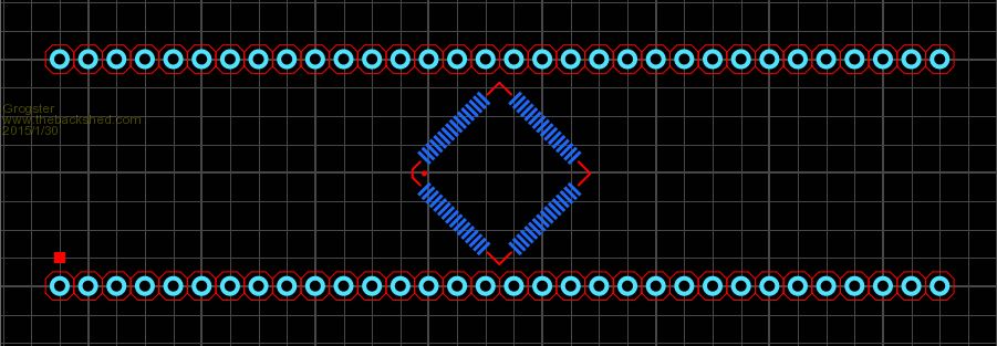
Smoke makes things work. When the smoke gets out, it stops! |
||||
