
|
|
Forum Index : Microcontroller and PC projects : Latching relay question....
| Page 1 of 2 |
|||||
| Author | Message | ||||
Grogster Admin Group Joined: 31/12/2012 Location: New ZealandPosts: 9975 |
Hi folks. 
I have some single-coil latching relays. These are the type where you put the juice on the coil one way, and the relay contacts close. To release, you have to put the juice on the relay coil in reverse polarity. There are plenty of ideas and circuits very similar to this one I found on the net: 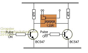
The theory is sound, and nice and simple etc. My only concern is back-EMF. Normally, in a relay circuit with a driver tranistor, you would put a back-EMF diode across the coil. However, that only works if the juice to the relay is always going to be in the same polarity - you can't do that with a coil where you flip the polarity around. So, can anyone suggest anything better, or perhaps a way to improve on this circuit I found? Perhaps I am being over-cautious, but back-EMF is a transistor-killer!  Smoke makes things work. When the smoke gets out, it stops! |
||||
| WhiteWizzard Guru Joined: 05/04/2013 Location: United KingdomPosts: 2991 |
G, How about using a low cost, high power MOSFET instead (of the NPNs)? These may withstand more of a 'bashing' - just my opinion mind - not based on any experience 
I've never come across this type of relay (only the dual coil latching type which I love to use). Have you got a supplier part number (or data sheet) link that I can look into? WW |
||||
disco4now Guru Joined: 18/12/2014 Location: AustraliaPosts: 1127 |
In this circuit wont the two 47 ohm resistor in series (94 ohm) that are effectively in parallel with the coil suppress the back-EMF voltage? Regards Gerry F4 H7FotSF4xGT |
||||
| twofingers Guru Joined: 02/06/2014 Location: GermanyPosts: 1761 |
@Grog, I think you are over-cautious. Just try and use a scope to find out the voltage level. If needed you can use two zener diodes parallel to the transistors. Regards Michael causality ≠ correlation ≠ coincidence |
||||
| matherp Guru Joined: 11/12/2012 Location: United KingdomPosts: 11512 |
You can use a bidirectional transient voltage suppressor (TVS) e.g P6KE7V5 would be suitable for 5V operation - they are available in a wide range of voltages |
||||
| MicroBlocks Guru Joined: 12/05/2012 Location: ThailandPosts: 2209 |
Only used dual coil. Works great and is super simple to connect. If you not already have a bunch of relays lying around then go for the dual coil ones. Microblocks. Build with logic. |
||||
| WhiteWizzard Guru Joined: 05/04/2013 Location: United KingdomPosts: 2991 |
I agree with you TZA but then Grogster's first words were . . . I have some single-coil latching relays. |
||||
| MicroBlocks Guru Joined: 12/05/2012 Location: ThailandPosts: 2209 |
:) You are right. I need another argument. :) What about: If you are going to make a PCB for it, then buy the dual coil ones. Make sure they are available later too. :) ;) :) Microblocks. Build with logic. |
||||
| Grogster Admin Group Joined: 31/12/2012 Location: New ZealandPosts: 9975 |
Heh, heh - thanks guys.
@ TZA: I hear you Re. the twin-coil latching relays, but as I have these single's here, I figured I might as well use them over buying yet more. @ disco4now: Yes, I think you are right there. Collapsing magnetic field will be reverse-polarity of supply voltage, and will effectively be shorted out via the two 47R load resistors - I must stop posting questions at 3AM my time - brain is half asleep, but fingers are still working...... 
@ WW: Here is a link to some on eBay - these are the exact same Panasonic ones I have here. Smoke makes things work. When the smoke gets out, it stops! |
||||
bigmik Guru Joined: 20/06/2011 Location: AustraliaPosts: 2981 |
Grogs, I have been intrigued by this question and the only idea I can come up with is to use a `snubber circuit' (resistor and capacitor in series) this circuit I would place across the collector and emitter of each transistor so that the EMF voltage would be shunted to GND until the capacitor charged. Regards, Mick PS. I did some googling and this has been a question that IMHO has not been answered clearly but has been asked many times over. Mik EDIT ** Personally I would avoid those relays.. Mick's uMite Stuff can be found >>> HERE (Kindly hosted by Dontronics) <<< |
||||
TassyJim Guru Joined: 07/08/2011 Location: AustraliaPosts: 6538 |
I would go with a back-EMF diode across each 47R resistor. For each 'direction', the diode will look like it's across the coil in series with the other 47R. That should protect the transistor but like most of the other responders, I don't like the circuit much at all and would prefer the two coil relays. If I has a draw full or them, I would be tempted to experiment... Jim VK7JH MMedit |
||||
| bigmik Guru Joined: 20/06/2011 Location: AustraliaPosts: 2981 |
Jim, The problem with that (as I see it) as there is no path to GND (when both transistors are off) for the Back EMF to take. It is a curly question that is for sure. Mick Mick's uMite Stuff can be found >>> HERE (Kindly hosted by Dontronics) <<< |
||||
| Grogster Admin Group Joined: 31/12/2012 Location: New ZealandPosts: 9975 |
...as we all know, twin-coil latching relays won't have this dilemma at all, as each coil has it's own transistor and back-EMF diode. I have about 40 or 50 of these relays in a box. I bought them ages ago, thinking that it may be handy to have some latching relays. Absolutely no thought whatsoever was given to how to drive them at the time! 
As per my usual motivation at the time - they were very cheap(but still new), so I thought: "I might need some latching relays one day", and grabbed them. I will experiment. EDIT: How about this revision of the circuit? 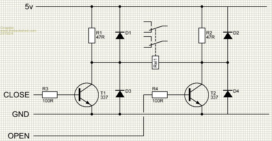
All diodes are standard 1A type. I stole this concept from the internal schematic of just about all H-bridge motor driver IC's. Those diodes should clip anything one would think. Thoughts? Opinions? Smoke makes things work. When the smoke gets out, it stops! |
||||
| akashh Senior Member Joined: 19/01/2014 Location: IndiaPosts: 115 |
I have been using these without any diode on one of my Wattmon modules and never faced a problem, the microcontroller never reset but of course that does not mean there wasn't a small spike. I put a 0.1 uf and a 100 uf next to the relay so perhaps that helped filter the spike. |
||||
| TassyJim Guru Joined: 07/08/2011 Location: AustraliaPosts: 6538 |
I did a spice simulation with 2 diodes. No idea what the inductance of the coil is so the actual spike size is irrelevant but two diodes (I used schottky diodes) did do the job. 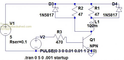
Drawing the circuit this way makes it look like a conventional relay control. For each direction, one diode is forward biased during the back emf period. Both diodes are reverse biased during the time the transistor is 'on' I would still like to do a real life test 'cos I don't trust my simulations that much. Conclusion - the relays Grogster has should be OK to use. Jim VK7JH MMedit |
||||
| TassyJim Guru Joined: 07/08/2011 Location: AustraliaPosts: 6538 |
If you drive them with a ULN2003 driver, the diode is already there. Just connect the common pin to 5V. When I looked at the link Grogster gave I thought they were a bit expensive - then I realised the price was for 10. Now they are interesting relays. Jim VK7JH MMedit |
||||
| Grogster Admin Group Joined: 31/12/2012 Location: New ZealandPosts: 9975 |
Yeah, about $1.15 each or so - not bad. Smoke makes things work. When the smoke gets out, it stops! |
||||
| larny Guru Joined: 31/10/2011 Location: AustraliaPosts: 349 |
Yes, that's right. If the supply voltage is 12 Volt, then the relay current will be 12/(120 + 47) = 72 mA. When the transistor is turned off, then this current will continue to flow initially & decay exponentially. The voltage across the 47 Ohm resistors will be 0.072 * 47 = 3.4 Volt. (i.e. 3.4 V across each resistor giving a total Back EMF of 3.4 * 2 = 6.8 V if measured between the 2 collectors) Thus the collector voltages will be 12 + 3.4 = 15.4 V for one transistor & 12 - 3.4 = 8.6 V for the other. Therefore neither transistor will be damaged. |
||||
redrok Senior Member Joined: 15/09/2014 Location: United StatesPosts: 209 |
Hi larny;Not quite. The relay, TXD2-L-4.5V, has a coil resistance of 135ohm. Lets use a supply voltage of 5V, load resistors of 47ohm, assume a VCEon of 0V, and initially eliminate the snubber diodes. The coil ON current will be: 5V / (135ohm + 47ohm) = 27.5mASince the peak current will be 27.5mA the voltage across the 2 resistors in series will be: 27.5ma * (47ohm * 2) = 2.58V for both However, each resistor will have only half of this: 2.58V / 2 = 1.29V on each.In this case: The driven transistor when turned off will have: 5V + 1.29V = 6.46V And the passive transistor will have: 5V - 1.29V = 3.71V And after the current collapses they will both have 5V.I agree. To go further: This example has a coil resistance of 135ohms. The spec says the relay has a "Pickup Voltage" of 75% of the rated voltage, 4.5V in this case: 75% * 4.5V = 3.375V relay pickup voltage in the spec. Lets calculate this circuit's pickup voltage: 5V * 135ohm / ( 47ohm + 135ohm) = 3.71V circuit's pickup voltage. Getting kind of close! Not quite high enough to meet speck but would probably work. I guess I would use a smaller resistor, possibly 43ohm or 39ohm. And of course one should figure in the tolerance of the 5V supply and the non 0V of the transistor. BTW, why not use the venerable 2N7000 MOSFET. Edit: I have to add a comment: The reason no snubber diodes are required in this example is there is no value of resistance pairs that will allow the the kickback voltage to go negative on the passive transistor nor greater than 2 times the voltage rail on the driven transistor. Cool huh!!! Of course, there are other problems but never reverse polarity. redrok |
||||
| larny Guru Joined: 31/10/2011 Location: AustraliaPosts: 349 |
Good morning redrok, I don't know why you wrote "Not quite" Gerry was right as the resistors are in parallel with the coil as far as the back EMF is concerned, i.e. 47 + 47 = 94 Ohm, thus the 94 Ohm is in parallel with the coil & the coil current decays through them. Larny |
||||
| Page 1 of 2 |
|||||
| The Back Shed's forum code is written, and hosted, in Australia. | © JAQ Software 2026 |
