
|
|
Forum Index : Microcontroller and PC projects : Zener diode
| Author | Message | ||||
| Sir_M Newbie Joined: 14/01/2013 Location: SwedenPosts: 15 |
Hi all Am I thinking right here? 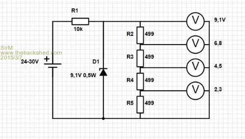
/ J |
||||
boss Senior Member Joined: 19/08/2011 Location: CanadaPosts: 268 |
@Sir_M Nothing wrong with your circuit. What is the purpose for? |
||||
redrok Senior Member Joined: 15/09/2014 Location: United StatesPosts: 209 |
Hi Sir_M; No. The four 499 ohm resistors in series draw quite a bit of current. So much so there will be none left to go through the regulating zener. I would suggest raising R2...R5 to 2K each. Or R1 can be lowered to 2.5K any you can still use the 499 Ohm resistors. R1 will need to be rated at least 1/4 watt. redrok |
||||
| Sir_M Newbie Joined: 14/01/2013 Location: SwedenPosts: 15 |
@Boss Thanks for reply. Basic programming is much easier than basic electronics 
Its for using a 0-10V analog input on a PLC for setting parameters with a dip-switch. The zener is for stabilize the voltage so I know that the resistor/voltage divider givexs the right input regardeless of source voltage (between 24-30V). / J @Redrok Ah, got it. Better to raise 499 to 2k to keep the overall consumption/heating as low as possible. /J |
||||
| boss Senior Member Joined: 19/08/2011 Location: CanadaPosts: 268 |
I recalculated your circuit. Basic design is O.K. but : (24V-9.1V)/10kOhm=1.5mA 1.5mA*500Ohm=0.75V which is wrong, you have to increase current at least 5mA that means @24-9.1)/.005=2700 Ohm (2k7) resistor Sorry for confusion, Regards Bo |
||||
Grogster Admin Group Joined: 31/12/2012 Location: New ZealandPosts: 9975 |
I'm probably missing something here, but if you need stable input voltages via switches to your PLC, why don't you use voltage regulators rather then a zener and potential divider? ...I guess if you want it as simple as possible, but I don't like zener regulators much...(but then, that makes me BIASED!!! Ha, Ha, Ha, Ha, Ha!!!!  ) )Smoke makes things work. When the smoke gets out, it stops! |
||||
| Sir_M Newbie Joined: 14/01/2013 Location: SwedenPosts: 15 |
@ Grogster 
Started with just a solution among others. Now it have become a basic school in electronics for me.
Wonder if I�ve got it right this time... 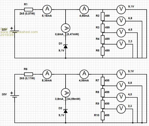
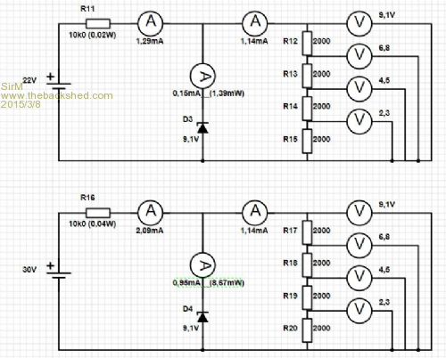
/ J |
||||
| redrok Senior Member Joined: 15/09/2014 Location: United StatesPosts: 209 |
Hi Sir_M; Yes, you have it right. I might suggest you change the 2.5K to 2.4K because 2.4K is a standard 5% value. The PLC I use supplies a regulated 24VDC output. Mine also has a 0V to 10V analog input. The input impedance of mine is 1M ohm so has little loading effect on the divider circuit. Presumably yours is also 1M ohm. If you have a regulated 24V output, as mine has, you may want to try: R1 = 5.6K and R2...R5 = 1K and eliminate the zener diode. This would then have taps at 0V, 2.5V, 5V, 7.5V, and 10V. (Within the 5% error of course.) Or R1 = 1.4K and R2...R5 = 499 and eliminate the zener diode. (assuming you have the 499 ohm 1% resistors.) This would then have taps at 0V, 2.5V, 5V, 7.5V, and 10V. (Within the 5% error of course.) redrok |
||||
| Sir_M Newbie Joined: 14/01/2013 Location: SwedenPosts: 15 |
Nopes, no regulated output, its mounted on a truck with 24V system. That was the reason that i found my self at Zener "school bench"
Thanks a lot for helping me out here / J |
||||
TassyJim Guru Joined: 07/08/2011 Location: AustraliaPosts: 6538 |
A while ago we (The Back Shed mob) did some experiments with zeners as input protection. It soon became obvious that they are not very precise as a voltage reference. The voltage drop is very dependent on the current flowing through the Zener. It would be best to use a 3 terminal regulator instead of the Zener. Jim VK7JH MMedit |
||||
| The Back Shed's forum code is written, and hosted, in Australia. | © JAQ Software 2026 |
