
|
|
Forum Index : Microcontroller and PC projects : MOSFET help....
| Author | Message | ||||
Grogster Admin Group Joined: 31/12/2012 Location: New ZealandPosts: 9547 |
Hi folks. 
I need a little MOSFET advise. I am a bi-polar transistor man, and that is what I was trained in, and have not really done much with MOSFET devices. However, I understand their advantages, and have found a case where I really need to use one over a transistor. I have a 3v RF module I need to switch the main supply to it via a MM. Using either a PNP or NPN transistor will drop the standard 0.6v, which with higher voltage stuff is not really a problem, but the lower voltage stuff really can not perform as expected, if you rob it of half a volt or more of supply. So, I was looking at using a P-channel MOSFET as a high-side switch, rather then a PNP transistor. The concept would appear to be the same: 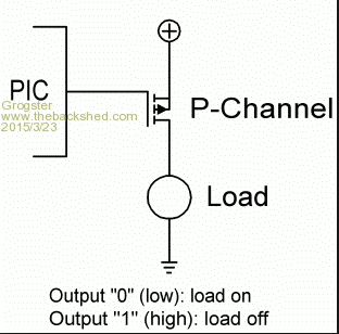
Logic low will switch the load on, logic high will switch the load off. Other then standard voltage and current ratings of the MOSFET, is there anything else I need to know to be able to use them? This one was the one I was thinking of using. Supply voltage is 3v3, load current of the transmitter is 50mA or less. As this MOSFET has a S-D resistance of 0.1 ohms, which is about standard, I should have practically no voltage-drop to the 3v transmitter module, if I use a MOSFET rather then a PNP transistor. As MOSFETS have such high-impedance gate's, I see some circuits(like the image above I stole from Google Images) that don't bother with the equivalent of a current limiting base resistor. Is that standard practice? Smoke makes things work. When the smoke gets out, it stops! |
||||
| viscomjim Guru Joined: 08/01/2014 Location: United StatesPosts: 925 |
Hi Grogster, I am using a p channel fet to power up the uMite. If you look at the second to last post in THIS thread, the only thing I changed is the 2n2222 transistor to a 2n7000 n channel mosfet (it's small) to switch the gate of the p channel power fet to ground to turn it on. WORKS GREAT!!! Just make the changes to power your module instead. Remember to pull the p channel fet gate high with a resistor to make sure it stays off when you want it to. |
||||
| Grogster Admin Group Joined: 31/12/2012 Location: New ZealandPosts: 9547 |
Here is a better image from Google: 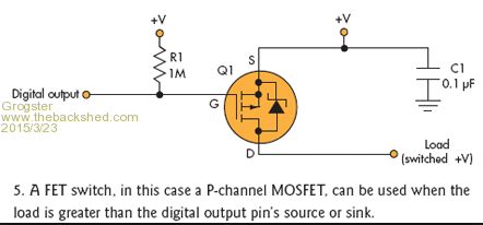
This image shows the internal diode, so it would be source to 3v3, drain to the RF module 3v3 supply input. Smoke makes things work. When the smoke gets out, it stops! |
||||
| robert.rozee Guru Joined: 31/12/2012 Location: New ZealandPosts: 2415 |
apart from supplying power to the load, is there any other connection to it such as a data input? if not, then low-side switching is so much simpler. the 0.6v drop you mention is the Vbe, which does not appear in series with the load. the Vce (collector to emitter) drop when a bipolar transistor is saturated (fully turned on) is minimal within the rated Ic, and in your application likely to be a small fraction of a volt; if using a BC337, Vce(sat) @ Ic/Ib=10 is less than 100mV for values of Ic less than 200mA. (https://www.onsemi.com/pub/Collateral/BC337-D.PDF , see figure 5) note that the BC337 is a useful switching device, far superior in this sort of application to a BC547, which has a much higher Vce(sat). the problem with your MOSFET circuit is that if power to the PIC is lost, then the MOSFET will turn on. similarly, the transmitter supply voltage can not be any higher than the PIC's supply, which may be a limitation. to use a MOSFET you need to use two transistors. an NPN transistor to create an open-collector output, then the P-ch MOSFET with a pullup on the gate. if the transmitter supply is more than about 8v you will also need a zener diode to protect the gate from excessive voltage. cheers, rob :-) |
||||
| Grogster Admin Group Joined: 31/12/2012 Location: New ZealandPosts: 9547 |
Hi folks.
Supply is 3v3 via regulator. Transmitter cannot run at more then 3v3, as it is on the same supply. Transmitter current is 25mA typical, but there is a carrier as soon as voltage is applied - there is no enable/disable pin as on some of the other modules I have used. Cannot use low-side switching, as the transmitter has to be earthed for stability, and their is more then one ground pin on the module - I don't know if you can have the module's ground floating, and just switch that a-la NPN on the low-side as per usual. Perhaps you can, but I am a little dubious of that idea where RF modules are concerned.... Transmitter is Radiometrix TX2H @ 434MHz.(25mW output) EDIT: Opps - forgot your question, Rob: YES - Data input pin also comes from the PIC. EDIT: What about using a 337 as an emitter-follower, and plopping the TX2H between the 337's E and ground? Smoke makes things work. When the smoke gets out, it stops! |
||||
| robert.rozee Guru Joined: 31/12/2012 Location: New ZealandPosts: 2415 |
yes, you could use the BC337 as an emitter follower, though then the emitter would sit 0.6v below the base, bringing in a 0.6v drop in the supply voltage to your transmitter. the following circuit is something i've used in the past, most recently to test the drop-out time for some mobile (13.8v) radio products - the company wanted to see how long a supply drop-out could be before the radio reset itself. the P-ch MOSFET i used was a bigun, needing to be able to switch something like 25A with minimal loss. the control signal came from an HP signal generator that allowed the creation of very precise negative-going pulses to simulate the dropout condition: 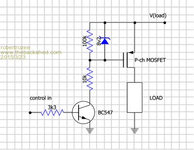
cheers, rob :-) |
||||
OA47 Guru Joined: 11/04/2012 Location: AustraliaPosts: 982 |
Grogs, I have mentioned before that I have used an opto-coupler to link a mosfet to the pic. Only requires 4 components, 2 resistors opto and mosfet. GM EDIT: Better make that 5 components -100n to eliminate spikes when mosfet switches. |
||||
| OA47 Guru Joined: 11/04/2012 Location: AustraliaPosts: 982 |
Here's the link to a part circuit: http://www.thebackshed.com/forum/uploads/GraemeMeager/2014-08-24_030111_solarshutdown.zip |
||||
| WhiteWizzard Guru Joined: 05/04/2013 Location: United KingdomPosts: 2927 |
Hi G, This has been mentioned/discussed in another thread but just can't remember which one. Anyway, I would personally use just one MOSFET and switch the 0v line which will then totally isolate the RF module. I will refer you again to the circuit diagram shown in June 2014 SC (Voice Recorder project). This is the edition containing Part II of Geoff's four part MicroMite series. Look at how they isolate the TFT and the SD card! Nice and simple - and I have used this exact same method numerous times (including isolating a RF12B RF unit!!) 
WW |
||||
redrok Senior Member Joined: 15/09/2014 Location: United StatesPosts: 209 |
Hi Grogster;You asked if the DMP2215L-7 would be suitable to switch power for your low powered RF module. Some have suggested alternate methods of doing this which may have merit in other applications. However, in your application: 1. The supply is 3.3V which powers both the uMite and the RF module. 2. The RF module must have a common ground because the uMite also controls the modulation. 3. The RF module runs at 25mA, possibly 50mA, a relatively low current. 4. The DMP2215L-7 has a worst case RDSon of 215mOhm. So the voltage drop at 50mA would be less than 11mV and dissipate less than 1mW. All very good. Even at 250mA the drop 5. Just to be sure the DMP2215L-7 stays off during power up a pullup resistor should be connected from the Gate to the Source. The value is not critical but 100K sounds about right. 6. Of course the software is up to you. I'm not completely familiar with the uMite but I think the pin will be an input on boot up. The first thing to do is output a high, then change the pin to an output, in this order. This should make sure the DMP2215L-7 will NOT be turned on even for an instant. ( Please correct me if this isn't correct. ) redrok |
||||
| srnet Senior Member Joined: 08/08/2014 Location: United KingdomPosts: 164 |
The PMV22 is one of the best of the small SOT P channel MOSFETS. It can handle 5A, switches very well at 3V and has a very low on resistance of around 22mR max. I used one in the power switch circuit on a PICAXE\RFM22B processor\radio board, its to allow a power down of the electronics as a protection against gate latchup. When its on the voltage drop across it was a measured 1.5mV @ 84mA. I have also used the IRLF6402 as a high side power switch controlling the power to a GPS. That works very well at 3V also. $50SAT is Silent but probably still working. For information on LoRa visit http://www.loratracker.uk/ |
||||
| redrok Senior Member Joined: 15/09/2014 Location: United StatesPosts: 209 |
Hi Grogster; I know your circuitry is already designed but I would be remiss if I didn't show a very nice all MOSFET H-Bridge: 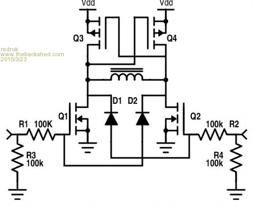
The high side DMP2215L-7 MOSFET would work well at 3.3V. The 2 diodes guarantee minimal shoot through in case both MOSFETs are enabled at the same time. When running it at higher voltages make sure the high side MOSFET maximum gate voltage is not exceeded. redrok Sorry, I posted this in the wrong thread. redrok |
||||
| Grogster Admin Group Joined: 31/12/2012 Location: New ZealandPosts: 9547 |
Hey folks.
I am now likely to use the 2305 MOSFET as Element14 are selling these at 8.4 cents each at the moment. S-D on resistance is only 60mOhms @ 4.5 v, and 90mOhms @ 2.5v, and can pass 3A or so if need be. Other then that, the only other change is the inclusion of the pull-up resistor to the gate to keep the MOSFET off during power-up. Is everyone relatively happy? Smoke makes things work. When the smoke gets out, it stops! |
||||
| robert.rozee Guru Joined: 31/12/2012 Location: New ZealandPosts: 2415 |
sounds like a good choice with Vcc of 3v3, along with the pullup resistor should do the trick nicely 
cheers, rob :-) |
||||
| Grogster Admin Group Joined: 31/12/2012 Location: New ZealandPosts: 9547 |
Cool.
Thanks everyone, for the advise. Smoke makes things work. When the smoke gets out, it stops! |
||||
| The Back Shed's forum code is written, and hosted, in Australia. | © JAQ Software 2025 |
