
|
|
Forum Index : Microcontroller and PC projects : pic32prog
| Author | Message | ||||
| robert.rozee Guru Joined: 31/12/2012 Location: New ZealandPosts: 2285 |
given that the PIC16F1455 would be talking USB in one direction (to the host PC), and ICSP in the other direction (to the target PIC32) would the serial layer be involved anywhere? when using the Arduino NANO, the serial link itself is just between the CH340G and the ATmega328P processor, the wires between the two being traces on the PCB that are less than 1/2 an inch long. i tried to design the 'ascii ICSP' protocol so that it would be flexible enough to (hopefully) program other PIC families. there are commands for clocking single bits directly out PGD ('0', '1'), clocking in a single bit ('-'), along with commands to control a Vpp output ('6', '7'). there is also a command ('@') to read back analog inputs. it has always been my hope that someone might make use of these commands to implement using the programming adapter to program other PIC families, perhaps modifying some of the existing PIC programming software out there that already exists for 8 and 16 bit PICs. cheers, rob :-) |
||||
| Chris Roper Senior Member Joined: 19/05/2015 Location: South AfricaPosts: 280 |
I have programmed lots of other PIC's but to be honest I have never even considered the intricacy's or differences. I have a PICKit2 permanently hooked up to my 8 Bit Development Board and a PICKit3 On the Board I use for PIC24/33/32 devices. So I just hit the Build Button and the Device gets programmed. It could be an interesting exercise to look at the newer device programming standards as I am sure they are probably the same as PIC32. It will still be necessary to support the older standard too though as Hobbyists are still working with many legacy devices that they can get ready made hex files to try out on. Looking forward to Rob's reply as he knows far more about programming protocols than the vast majority of PIC users 
Cheers Chris http://caroper.blogspot.com/ |
||||
| MicroBlocks Guru Joined: 12/05/2012 Location: ThailandPosts: 2209 |
In my particular case i would really like the USB-Serial converter to act as a programmer for te other microcontroller parts i want to use. It will be limited by hardware design to devices that can be programmed with a Vpp that is either 5v or 3v3 (Same as the chips Vdd). My understanding on a not too deep level is that the main change was caused by using flash memory instead of eeprom which used higher voltages. Then another change occurred by using a specific sequence on the MCLR pin to enter programming mode. The rest is just using PGD and PGC to clock in data. I am not sure as i have not read the specific information yet to know if PGD and PGC are handled differently once programming mode is established. The PIC16F1455 has after it is loaded with the USB-Serial software 569 bytes of RAM and 4789 bytes of Flash free. Looking at the code for the uno i would say that it would fit, only less RAM will be available which should lower its buffer capacity. A bigger buffer does not always mean lower performance as once as buffer is full the slowest part will probably still be the manipulation of the pins. This result is with the free version of the MPlabX XC8 compiler. It could be much less with the pro compiler. it says: You have compiled in FREE mode. Using Omnicient Code Generation that is available in PRO mode, you could have produced up to 60% smaller and 400% faster code. See http://www.microchip.com/MPLABXCcompilers for more information. As i want my 'Microblocks' to be open as much as possible i would like to use freely available compilers. But if push comes to shove and i have to lower quality or functionality i will bite the bullet and buy the Pro version. The hex file will stay free but it would then be semi open. Which at such a moment would be a good tradeoff. The whole idea that a tiny USB-Serial module can be 'hacked' to fulfill your needs is great. I want to do that with every 'block' that has an mcu on it. This will keep the possibilities of the 'blocks' much more versatile as i am sure there are people out there that have much better ideas then me. I'll shut up about the 'blocks' in this thread from now because it certainly is not about that, i just want to let you know what my personal wishes are that i would like to accomplish. Microblocks. Build with logic. |
||||
| robert.rozee Guru Joined: 31/12/2012 Location: New ZealandPosts: 2285 |
alas, i know very little! much of the work i've done with pic32prog has consisted of splicing together and adapting pieces of code others have written, and following 'recipes' in microchip datasheets. my C programming skills are mediocre at best.l i did look at the PIC16f628 a while back, for use instead of the Arduino NANO, and found that the programming algorithm was considerably more simplistic than that of the PIC32 family: the PIC32 devices implement a quite complicated JTAG state machine, that is wrapped up in a further ICSP layer; programming flash requires pushing machine instructions out to the PIC32 and having them run one instruction at a time. in contrast, the lesser PIC families are treated more akin to programming an eeprom - you load a starting address, then send out repeated 'write' instructions that carry the data. my plan when i looked into it was to use the handshaking lines of a serial port to bootstrap the 'ascii ICSP' code into the PIC16f628, but in the end i decided it was a step too far. the Arduino NANO was just so cheap, and the Arduino IDE so simple to get up and running. however, what i can say for sure is that the hardware required to program any of the PIC families is far simpler than looking at a PICkit 2 or 3 would lead you to believe. both PICkit 2 and PICkit 3 have embedded in them layers of complexity that could just as easily be handled by the host PC. this leads me to wonder - why? it is as if microchip sees themselves making a significant portion of their profit selling programming hardware, or alternatively sees some compelling reason to try to lock developers into having to purchase microchip programmers and use microchip software tools. cheers, rob :-) |
||||
| MicroBlocks Guru Joined: 12/05/2012 Location: ThailandPosts: 2209 |
What i know about Microchip is that they have an incredible amount of diversity in their offerings. This alone already causes the differences in design etc. Lots of chips are already of old design, but they still keep them as it seems there is still a need for them. I guess lots of appliance manufacturers just keep their electronics the same. As a hobbyist and small projects maker i love the amount of choice. But i also tend to use the newer line of chips which seems te be more alike. Having bought a pickit2 somewhere around the end of 2005 and bought a pickit3 about at least a year ago i never felt i had to spent too much money. 100 US$ combined over 10 years seams reasonable. For programming i agree there should be (and there are) cheaper solutions. The real value for me in these Pickits is that i can use them for debugging. The pickit3 works pretty well for that. That and if i mess up something or need to learn there are a lot of topics on forums that discuss these things. Having a cloned pickit for debugging, the standard answer is 'Do you have a genuine pickit3'. That does not get you far. 
For people who just enter this area it can be steep. One of the reasons i like the use of the nano. Easily available and you then have a useable Nano AND a pic32 and money left for some other stuff. Once i read the sourcecode for the USB-Serial and your code for the nano a few more times and i have a the right mosfet i will try to port the code. I also have lots of pro-micro's lying around. That has a ATMega 32U4 processor that has USB built in. I think your code will run on that one too without to much modifications. edit: I found the programming document for the PIC16(L)F145sx chips here. Got some more bedtime reading. 
Microblocks. Build with logic. |
||||
| MicroBlocks Guru Joined: 12/05/2012 Location: ThailandPosts: 2209 |
@Rob, I have studied your bitbang routines that run in the Nano and i was wondering about a few things. I can see that you started with a 'human readable' format. This readable format has room enough for sending 4 bits at a time encoded in 'i' to 'x'. I did not study the pic32prog program yet so i am not sure about the protocol. What i see in the Nano software is that when a 'i' to 'x' character is received it is clocked into the chip but does not return any data. Does that mean you send a bunch of those characters without the nano sending feedback. If that is true would it then be possible to use a STX followed by a byte that tells how many bytes of data will follow, then those databytes and finish with a checksum. This will be almost the same as what is in a HEX file. But that will only work if you can send at least 1 and maximum 16 bytes in one time without the need to send data back to the pic32prog.exe. You can see, i not really 'got it' yet.
Would it be possible for you to make a small PIC32 program (Maybe a blink led) and then dump all the bytes send and received to and from the Nano into a file together with the HEX file for me to study? I don't have a Nano yet, i will try to port it to a Pro Micro in the meantime. Microblocks. Build with logic. |
||||
| robert.rozee Guru Joined: 31/12/2012 Location: New ZealandPosts: 2285 |
here are a couple of trace outputs from pic32prog: 2015-09-12_145951_1bit.zip 2015-09-12_150015_4bit.zip (if using windows, open the .txt files within using wordpad) 1bit.zip contains the data exchanged between pic32prog and the NANO when 4-bit compression is turned off. the actual data sent/received is shown within pairs of brackets <> while the remainder of each line is other debug information. a few (5) example lines are: n=40, <edd.dddddddfddffdfdffffddddddfdfffddg.ed> read=0 TDI: 0000 0001 3a07 ac80 n=40, <edd.dddffdddfdddfffffddddddddfdfffddg.ed> read=0 TDI: 0000 0001 3a01 f118 n=14, <e.edd.dfdfe.ed> read=0 TDI: 0000 0000 0000 000a n=39, <edD.DDDDDDDDDDDDDDFFDDFDDDDDDDDDDDDe.ed> read=1 TDI: 0000 0000 0004 c000 TDO = 0000 0000 400c c008 (32 bits) <00010000000000110011000000000010> the first 3 are write-only lines sent to the NANO, while the 4th line requests responses and the 5th is the response from the NANO. the 3rd line has a 1-bit command at the beginning (the others contain no command portion). note that upper-case letters denote a response is expected for a given symbol, while lower-case denotes no response. the read-flag applies on a per-bit basis. generally, the format is "command.header.data.footer", where command is not always required, and header and footer are only present when there is 1 or more data bits. 4bit.zip contains the data exchanged when 4-bit compression is turned on. a sample (of the same 5) lines are: n=13, <a.iquspislg.z> read=0 TDI: 0000 0001 3a07 ac80 n=13, <a.qjjxjislg.z> read=0 TDI: 0000 0001 3a01 f118 n=8, <e.a.se.z> read=0 TDI: 0000 0000 0000 000a n=15, <A.IIIUMIIDDDe.z> read=1 TDI: 0000 0000 0004 c000 TDO = 0000 0000 0000 c008 (32 bits) <0MIIOIII000> the vast majority of exchanges are write-only, being of the form: n=40, <edd.dddddddfddffdfdffffddddddfdfffddg.ed> read=0 TDI: 0000 0001 3a07 ac80 or n=13, <a.iquspislg.z> read=0 TDI: 0000 0001 3a07 ac80 (4-bit encoded) so there are mostly 32 bits of actual data encoded into 11 characters (the dots don't count - they are just there to make the output more readable and are not normally generated). while the data could be compressed more, this comes at the expense of significantly complicating the code in the NANO and making the whole protocol far less flexible. going much beyond the (4-bit + read flag) compression of data would quickly run into diminishing returns. cheers, rob :-) |
||||
| MicroBlocks Guru Joined: 12/05/2012 Location: ThailandPosts: 2209 |
Thanks Rob. That clarifies some things i was struggling with. I managed to use the SOF messages that come from the USB every 1ms to act as a timer for a statemachine. As everything is polled at the moment i need to finish the ;work' withing 1ms. If it takes longer i just use the states and counters to split up the work. Most commands seem to work easily within that time. Some have 1 microsecond and then only a few in a singlecommand. That falls well below the threshold to not disturb USB polling. The one that needs some timeslicing are as far as i can see command '6','7' and of course '8'. The '@' command is just for other test purposes i assume. I have got it to respond to a '>' and also the '?'. What i did to switch between USB-Serial and Programming mode is that within 2 seconds after asserting DTR at least 10 '>' are expected. If that is not received then it goes into the USB-Serial mode. This saves using a pin as the 1455 does not have many to begin with. 
The USB part is hard to debug and lots of it is unknown territory so i have to do it bit by bit. At least the demo code from Microchip works pretty well. One concern is the amount of memory that is available. I can reuse the serial in and out buffers and allocate some more for when it is in programmer mode, but i think i can not get up to 1024 bytes. More like 512 or if i can keep it small maybe 768 bytes. I forked your version of pic32prog and i can add the code (when it is stable) for the pic in a separate folder if you want. Maybe a folder under the bitbang folder? Microblocks. Build with logic. |
||||
| MicroBlocks Guru Joined: 12/05/2012 Location: ThailandPosts: 2209 |
Made a little progress. Have some commands that control the output voltage and #MCLR signal working. State machine is working sofar and i am confident that i will be able to port the complete Nano code. Not much time though at the moment so i do a little bit every day. I don't have a compiler to recompile pic32prog, but if all works well then it only needs a few lines of code to toggle the DTR. I will first make it work with the current version and use the same identification string as the Nano. Microblocks. Build with logic. |
||||
| MicroBlocks Guru Joined: 12/05/2012 Location: ThailandPosts: 2209 |
It works! [code] C:\Users\mail\Dropbox\Micro Blocks\Projects\BreadBoard\U2SP5\Software\pic32prog> pic32prog -d ascii:com4 mm.hex Programmer for Microchip PIC32 microcontrollers, Version 2.0.157 Copyright: (C) 2011-2015 Serge Vakulenko (ascii ICSP coded by Robert Rozee) Adapter: .......... OK1 OK2 - ascii ICSP v1E Processor: MX170F256B Flash memory: 256 kbytes Boot memory: 3 kbytes Data: 258712 bytes Erase: (110mS) done Loading PE: 1 2 3 4 (LDR) 5 6 7a (PE) 7b 8 v0301 Program flash: ################################################# done Program boot: ####### done Verify flash: ################################################# done Verify boot: ####### done Program rate: 1284 bytes per second total TDI/TMS pairs sent = 3189378 pairs total TDO bits received = 506920 bits maximum continuous write = 934 chars O/S serial writes = 97031 O/S serial reads (data) = 15851 O/S serial reads (sync) = 1589 XferFastData count = 58606 10mS delays (E/X/R) = 11/0/0 elapsed programming time = 3m 24s [/code] The PIC16F1455 memory use is 550 bytes RAM out of 1024 bytes and 4736 bytes of Program Flash out of 8192 bytes. It also functions as a USB to Serial. Currently i have it for test purposes waiting maximum 20 seconds for ten '>' characters after it is plugged into the USB port. My preferred use would be to use the DTR to switch between modes. So if DTR is asserted and 10 '>' are seen within 2 seconds it switches to Programmer mode, if not then it defaults to USB to serial. Using the DTR keeps all the pins free, and no more need to remove the USB cable and reset the comport. Here it is connected with Mick's MUP. Now your PIC32 chips can be programmed through USB without a bootloader.
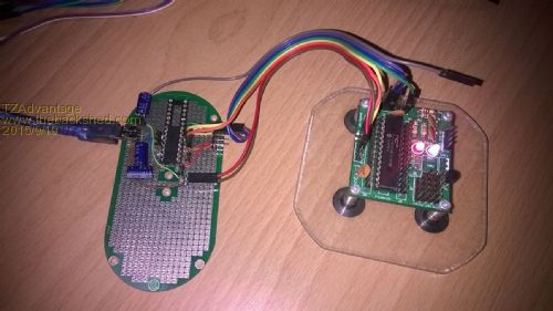
As you can see power, serial and ICSP are all wired and no more need to take out these cables. When using MMEdit you can use the DTR to reset the uMite. The USBtoSerial will stay connected so you will not loose connection anymore when you have to reset. Here is the code. I added a few functions to keep it more in line with the Arduino code. Manipulating the pins directly instead through a function might increase the speed a bit. But honestly. If i not have to start MPIDE,load the hex file, choose the right options etc it is already much faster. [code] //Arduino routines to help the port of the NANO source code void digitalWrite(PINNAMES pin, PORTBIT bitValue) { switch(pin){ case LED: LATAbits.LATA4 = bitValue;break; case ERRORLED: LATAbits.LATA5 = bitValue;break; case VCC: LATCbits.LATC2 = bitValue;break; case MCLR: LATCbits.LATC3 = bitValue;break; case PGC: LATCbits.LATC1 = bitValue;break; case PGD: LATCbits.LATC0 = bitValue;break; } } INT8 digitalRead(PINNAMES pin) { switch(pin){ case PGD: return PORTCbits.RC0; } return 0; } void AI_pinMode(PINNAMES p, PINMODES m){ switch(p) { case LED: TRISAbits.TRISA4 = m;break; case ERRORLED: TRISAbits.TRISA5 = m;break; case VCC: TRISCbits.TRISC2 = m;break; case MCLR: TRISCbits.TRISC3 = m;break; case PGC: TRISCbits.TRISC1 = m;break; case PGD: TRISCbits.TRISC0 = m;break; } } //Ported NANO code. Original made by Robert Rozee. int LEDxx = 0; // LED blink counter int PrAcc = 1; // accumulated PrAcc flag void AI_Setup() { digitalWrite(PGC, LOW); // PGC, open collector /w 3k3 pullup digitalWrite(PGD, LOW); // PGD, open collector /w 3k3 pullup digitalWrite(MCLR, LOW); // MCLR, open collector /w 3k3 pullup AI_pinMode(PGC, OUTPUT); // PGC = 0 AI_pinMode(PGD, OUTPUT); // PGD = 0 AI_pinMode(MCLR, OUTPUT); // MCLR = 0 digitalWrite(RST, HIGH); digitalWrite(Vpp, LOW); digitalWrite(LED, HIGH); digitalWrite(ERRORLED, LOW); AI_pinMode(RST, OUTPUT); // not MCLR (to drive base of NPN OC) AI_pinMode(Vpp, OUTPUT); // Vpp enable output (use optocoupler) } BYTE clock1(BYTE D) { AI_pinMode(PGD, (D != 0) ? INPUT : OUTPUT); AI_pinMode(PGC, INPUT); // HIGH (via 3k3 pullup) AI_pinMode(PGC, OUTPUT); // LOW char ch = '0' + digitalRead(PGD); return ch; } BYTE clock4( BYTE TDI, BYTE TMS) { // phase 1 AI_pinMode(PGD, (TDI != 0) ? INPUT : OUTPUT); AI_pinMode(PGC, INPUT); AI_pinMode(PGC, OUTPUT); // phase 2 AI_pinMode(PGD, (TMS != 0) ? INPUT : OUTPUT); AI_pinMode(PGC, INPUT); AI_pinMode(PGC, OUTPUT); // phase 3 AI_pinMode(PGD, INPUT); AI_pinMode(PGC, INPUT); AI_pinMode(PGC, OUTPUT); // read TDO BYTE B = digitalRead(PGD); // phase 4 AI_pinMode(PGC, INPUT); AI_pinMode(PGC, OUTPUT); return B; } //Process on character from the buffer. //Return values 0, '0', '1', 'I' - 'X' //Special return value ? to provide Product/Software Identification char loop(char I) { if (LEDxx == 0) digitalWrite(LED, HIGH); // turn status LED ON if (LEDxx == 3) digitalWrite(LED, LOW); // turn status LED OFF LEDxx = ++LEDxx & 0x001F; char ch = 0; if (((I >= 'i') && (I <= 'x')) || ((I >= 'I') && (I <= 'X'))) { // 4-bit encoding of TDI, TMS = 0 BYTE J = (I - 'i') & 15; BYTE B = 0; if (clock4(J & 1, 0)) B |= 1; if (clock4(J & 2, 0)) B |= 2; if (clock4(J & 4, 0)) B |= 4; if (clock4(J & 8, 0)) B |= 8; if (I <= 'X') { ch = 'I' + B; // 'I' <= ch => 'X' } return ch; } switch (I) { // 'd','e','f','g': write TDI and TMS, no read back case 'd': clock4(0, 0); return 0; // TDI = 0, TMS = 0, read_flag = 0 case 'e': clock4(0, 1); return 0; // TDI = 0, TMS = 1, read_flag = 0 case 'f': clock4(1, 0); return 0; // TDI = 1, TMS = 0, read_flag = 0 case 'g': clock4(1, 1); return 0; // TDI = 1, TMS = 1, read_flag = 0 case 'a': clock4(0, 1); clock4(0, 0); // TDI = 0, TMS = 1-0-0, read_flag = 0 clock4(0, 0); return 0; case 'z': clock4(0, 1); clock4(0, 0); // TDI = 0, TMS = 1-0, read_flag = 0 return 0; // 'D','E','F','G', '+': write TDI and TMS, read back TDO case 'D': return '0' + clock4(0, 0); // TDI = 0, TMS = 0, read_flag = 1 case 'E': return '0' + clock4(0, 1); // TDI = 0, TMS = 1, read_flag = 1 case 'F': return '0' + clock4(1, 0); // TDI = 1, TMS = 0, read_flag = 1 case 'G': return '0' + clock4(1, 1); // TDI = 1, TMS = 1, read_flag = 1 case 'A': clock4(0, 1);clock4(0, 0); // TDI = 0, TMS = 1-0-0, read_flag = 1 return '0' + clock4(0, 0); case '+': if (clock4(0, 0)) { // TDI = 0, TMS = 0, accumulate PrAcc PrAcc = 0; // remember if any error ('0') } return 0; // '>', '.', '=': handshake and formatting commands, placed here for possible speed case '>': return '<'; // request a sync response of '<' case '=': ch = PrAcc ? '1' : '0'; // retrieve value of PrAcc PrAcc = 1; return ch; case '.': return 0; // no operation, used for formatting // '0','1': used to clock out "MCHP" signature for ICSP entry case '0': clock1(0); return 0; // clock out a 0 bit on PGD pin case '1': clock1(1); return 0; // clock out a 1 bit on PGD pin case '-': return ch = '0' + clock1(1); // clock in single PGD bit // '2','3': pulse MCLR high, clock out signature, set MCLR high case '2': AI_pinMode(MCLR, OUTPUT); return 0; // set MCLR low case '3': AI_pinMode(MCLR, INPUT); return 0; // set MCLR high // '4','5': control power supply to target case '4': // turn power to target OFF AI_pinMode(PGC, OUTPUT); // PGC = 0 AI_pinMode(PGD, OUTPUT); // PGD = 0 AI_pinMode(MCLR, OUTPUT); // hold target in reset AI_pinMode(VCC, INPUT); // hi-Z return 0; case '5': // turn power to target ON AI_pinMode(PGC, OUTPUT); // PGC = 0 AI_pinMode(PGD, OUTPUT); // PGD = 0 AI_pinMode(MCLR, OUTPUT); // hold target in reset digitalWrite(VCC, HIGH); // Vcc AI_pinMode(VCC, OUTPUT); // Positive voltage determined by jumper (3.3v or 5v)) return 0; // miscellaneous other commands case '8': LastDelay = 10; return 0; // insert 10mS delay case '?': return '?'; // return ID string, "ascii ICSP v1X" default: digitalWrite(ERRORLED, HIGH); return 0; // invalid input - Turn on LED } // end of switch } // end of function loop() [/code] Microblocks. Build with logic. |
||||
| MicroBlocks Guru Joined: 12/05/2012 Location: ThailandPosts: 2209 |
@Rob, Would it be possible for you to pulse the DTR? I think the best place is here: [code] // // Serial port now open and configured. // //Pulse DTR (10ms is more than long enough) //Pause for 50 milliseconds. printf (" Adapter: "); [/code] Maybe for backward compatibility only use DTR when a -UseDTR is added to the command line. If it has no effect on the Nano then that would not be necessary. And if i may ask. I would very much appreciate if you could add the ProductID. I now use the same string as the Nano but that does not feel right. 
The ProductID is "MicroBlocks - U2SPxxx" The code stands for U - USB 2 - to S - Serial P - Programmer the 'xxx' are for future additions, in use now is U2SP5a. I am working on a U2SPH5a. The 'H' stands for HID and the '5' for 500ma version. The 5 could also be replaced by a 1 (125ma) or a 2(250ma) depending on which voltage regulator is needed. The last 'a' is the version. As long as it starts with 'U2SP' it will have the ascii ICSP function available. Microblocks. Build with logic. |
||||
| Chris Roper Senior Member Joined: 19/05/2015 Location: South AfricaPosts: 280 |
This is great ZTA, well done and a big thank you
If I may ask a couple of questions or suggestions: Are you allocating the same or different pins for PGC/PGD and Tx/Rx ? I ask because it would be nice if both the ICSP and the Serial Connections could be permanently connected. If they were then the PGC/PGD lines could be made High Impedance after programming to free up the target device pins. Secondly Have you, or would you be able to, add an LED or two to indicate traffic? An LED to indicate Tx and Rx could do dual duty and Indicate programming in progress and a pass/fail indication. I will Flash a 16F1455 with your code and start playing with it tomorrow, (after the F1 Race ).
Do you have a HEX file available, it would save some time ? If not I will finaly have to cave in to Microchip, jump through the hoops and install MPLABX it will be worth it now that I have a valid reason though, and I would probably need it for CFunctions too, so not a waist of effort I guess.
Cheers Chris and once again  http://caroper.blogspot.com/ |
||||
| robert.rozee Guru Joined: 31/12/2012 Location: New ZealandPosts: 2285 |
well done!
you should test with this version of pic32prog, that was uploaded earlier in the thread: 2015-08-29_154240_pic32prog.zip the .157 version you are using does not use the 4-bit data compression. while my fork contains the latest source code, the executable files are the old (1C) versions. i can not easily fix this, and am still waiting on serge to accept the version 1E changes and create new executable files. apart from the change from 500,000 baud to 115,200 baud, the protocols are backwards compatible, hence why the .157 executable works. the serial library, written by serge, does not have support for manipulating the serial port handshaking lines. you would need to add this support to serial.c for win32, linux, and OS X, then submit your changes to serge's master branch. then you would need to submit changes to adapter-bitbang.c to make use of the new functions. alas, the necessary coding is well beyond my abilities. there are also some situations where the OS may pulse DTR of its own accord, which would cause your planned usage to be unexpectedly triggered. the ID string identifies the protocol, not the product. to date there exists: 'iscii ICSP v1C' - original release. 500,000 baud, no data packing 'iscii ICSP v1D' - development code. 115,200 baud. uses RLL compression of data 'iscii ICSP v1E' - current release. 115,200 baud. used 4-bit encoding of data note: 1D had very limited distribution. RLL compression only reduced the data stream by about 50%, whereas 4-bit encoding achieved about 70%. 1D was more about proving that a reduction to 115,200 baud fixed issues with linux (and OS X). as the ID string identifies the protocol, and not the product, making changes would just add complexity. in all important regards it looks like you are closely following the 1E protocol requirements, and are therefore justified in returning the 'ascii ICSP v1E' ID string. there are just a couple of changes needed in your code, bugfixes made after you downloaded the sources from github: char ch = '0' + digitalRead(PGD); return ch; in clock1() should be BYTE B = digitalRead(PGD); return B; and case '+': if (clock4(0, 0)) { needs changing to case '+': if (!clock4(0, 0)) { both these bugfixes are in functions that are not currently used by pic32prog. they exist only in the source code, not in any of the executable files available. cheers, rob :-) |
||||
| MicroBlocks Guru Joined: 12/05/2012 Location: ThailandPosts: 2209 |
yes that version is a bit faster.
[code] C:\Users\mail\Dropbox\Micro Blocks\Projects\BreadBoard\U2SP5\Software\pic32prog> pic32prog -d ascii:com4 mm.hex Programmer for Microchip PIC32 microcontrollers, Version 2.0.BETA (30-08-2015) Copyright: (C) 2011-2015 Serge Vakulenko (ascii ICSP coded by Robert Rozee) Adapter: .......... OK1 OK2 - ascii ICSP v1E Processor: MX170F256B Flash memory: 256 kbytes Boot memory: 3 kbytes Data: 258712 bytes Erase: (110mS) done Loading PE: 1 2 3 4 (LDR) 5 6 7a (PE) 7b 8 v0301 Program flash: ################################################# done Program boot: ####### done Verify flash: ################################################# done Verify boot: ####### done Program rate: 1950 bytes per second total TDI/TMS pairs sent = 3304781 pairs total TDO bits received = 606728 bits total ascii codes sent = 1043405 total ascii codes recv = 208592 maximum continuous write = 911 chars O/S serial writes = 100150 O/S serial reads (data) = 18970 O/S serial reads (sync) = 5 XferFastData count = 58606 10mS delays (E/X/R) = 11/0/0 elapsed programming time = 2m 14s [/code] I have updated the code with your changes. I first thought it was a Product Identifier, but indeed it is a Protocol Version. Now that i have got it working i can tweak the code for speed. Microblocks. Build with logic. |
||||
| MicroBlocks Guru Joined: 12/05/2012 Location: ThailandPosts: 2209 |
Ok after tweaking the code a bit i got this: [code] C:\Users\mail\Dropbox\Micro Blocks\Projects\BreadBoard\U2SP5\Software\pic32prog> pic32prog -d ascii:com4 mm.hex Programmer for Microchip PIC32 microcontrollers, Version 2.0.BETA (30-08-2015) Copyright: (C) 2011-2015 Serge Vakulenko (ascii ICSP coded by Robert Rozee) Adapter: .......... OK1 OK2 - ascii ICSP v1E Processor: MX170F256B Flash memory: 256 kbytes Boot memory: 3 kbytes Data: 258712 bytes Erase: (110mS) done Loading PE: 1 2 3 4 (LDR) 5 6 7a (PE) 7b 8 v0301 Program flash: ################################################# done Program boot: ####### done Verify flash: ################################################# done Verify boot: ####### done Program rate: 3609 bytes per second total TDI/TMS pairs sent = 3480383 pairs total TDO bits received = 758600 bits total ascii codes sent = 1105103 total ascii codes recv = 260798 maximum continuous write = 911 chars O/S serial writes = 104896 O/S serial reads (data) = 23716 O/S serial reads (sync) = 5 XferFastData count = 58606 10mS delays (E/X/R) = 11/0/0 elapsed programming time = 1m 12s [/code] Not bad for burning the latest beta30 into a PIC32MX170 in 1 minute 12 seconds.
I think i can shave off a few seconds more. The main change is that i now use port A4 and A5 which have internal pullups. I can now connect a MUP without any extra parts. After programming is finished the A4,A5 and C3 pins which are connected to the ICSP pins PGC,PGD and #MCLR return to inputs with high impedance so they should not influence the normal use of the pins on the target. This is still with the FREE XC8 compiler in MPLAB-X. Memory usage is now 550 bytes RAM and 4544 bytes Flash. Microblocks. Build with logic. |
||||
| robert.rozee Guru Joined: 31/12/2012 Location: New ZealandPosts: 2285 |
wow, that is impressively fast! 
some quick calculations for the Arduino NANO version, where the serial port runs at 115,200 baud, gives a minimum theoretical programming time of: 1105103 (characters) * 10 (bits each) / 115200 (baud) = 96 seconds, or 1m 36s. clearly the PIC16F1455 via pure USB is beating this by a fair margin. were you able to make any optimizations in my C code? i've just been through and change all my ints to bytes, but alas that made no material difference. it could well be that the Arduino version is topping out because of the serial port library overhead. cheers, rob :-) |
||||
| MicroBlocks Guru Joined: 12/05/2012 Location: ThailandPosts: 2209 |
The biggest change was when i changed from switching between input/output to simulate a OC pin with external pull up (like the nano) to using pins in output mode and only changing the pins to input (with internal pullup) when needed. I had to move PGC and PGD to PORTA as that port supports internal pullups. The PIC16F1455 has an operating voltage range of 2.3v until 5.5v so i do not need real open collector outputs as it does not need to provide voltages that are out of this range when programming PIC32s which are all 3.3v. So i have to go through the code again to assign the target VCC pin and LEDS. FAST_PGC and FAST PGD are defines to the Latch registers. [code] #define FAST_PGC LATAbits.LATA4 #define FAST_PGD LATAbits.LATA5 #define FAST_MCLR LATCbits.LATC3 #define FAST_READ_PGD PORTAbits.RA5 [/code] [code] void AI_pinMode(PINNAMES p, PINMODES m){ switch(p) { //case LED: TRISAbits.TRISA4 = m;break; //case ERRORLED: TRISAbits.TRISA5 = m;break; //case VCC: TRISCbits.TRISC2 = m;break; case MCLR: TRISCbits.TRISC3 = m;break; case PGC: TRISAbits.TRISA4 = m; WPUAbits.WPUA4 = m == INPUT ? 1 : 0; break; case PGD: TRISAbits.TRISA5 = m; WPUAbits.WPUA = m == INPUT ? 1 : 0; break; } } void AI_Setup() { FAST_PGC = 0; FAST_PGD = 0; FAST_MCLR = 0; AI_pinMode(PGC, OUTPUT); AI_pinMode(PGD, OUTPUT); AI_pinMode(MCLR, OUTPUT); } void clockOut1(BYTE D) { FAST_PGD = D; FAST_PGC = 1; FAST_PGC = 0; } BYTE clockIn1(BYTE D) { AI_pinMode(PGD, INPUT); FAST_PGC = 1; FAST_PGC = 0; BYTE B = FAST_READ_PGD; AI_pinMode(PGD, OUTPUT); return B; } BYTE clock4( BYTE TDI, BYTE TMS) { // phase 1 FAST_PGD = TDI; FAST_PGC = 1; FAST_PGC = 0; // phase 2 FAST_PGD = TMS; FAST_PGC = 1; FAST_PGC = 0; // phase 3 AI_pinMode(PGD, INPUT); FAST_PGC = 1; FAST_PGC = 0; // read TDO BYTE B = FAST_READ_PGD; // phase 4 FAST_PGC = 1; FAST_PGC = 0; AI_pinMode(PGD, OUTPUT); Set it back to output for the next call return B; } [/code] My next attempt to gain more speed is to change this: [code] if (clock4(J & 1, 0)) B |= 1; if (clock4(J & 2, 0)) B |= 2; if (clock4(J & 4, 0)) B |= 4; if (clock4(J & 8, 0)) B |= 8; [/code] into one function call. [code] not implemented yet: B = clock16(J); [/code] This will save function calling/stacks handling/if statements expressions overhead on the most often used part of the program. Microblocks. Build with logic. |
||||
| matherp Guru Joined: 11/12/2012 Location: United KingdomPosts: 8567 |
TZ When you are happy with the code I can compile it "O2" for you if you want to test it |
||||
| MicroBlocks Guru Joined: 12/05/2012 Location: ThailandPosts: 2209 |
Thanks! It is already getting close to the maximum theoretical speed which makes me actually wonder how much improvement a PRO version will give. Maybe going to a higher baudrate will reveal where the bottleneck is. I still have to figure out how the IO pins are implemented in hardware inside the PIC. As using the pins as outputs has the risk of having two outputs, one on the programmer side and one on the target being opposite values creating basically a 'short'. This will be of extreme short duration but still it is not the proper way to do it. As this is now specific for programming a PIC32 i have to look at both chips datasheet and see at what time the target PIC changes it PGD to an output. If i can time it that right before that happens i can change it on the programmer side to an input it would be save. Microblocks. Build with logic. |
||||
| MicroBlocks Guru Joined: 12/05/2012 Location: ThailandPosts: 2209 |
ok, So i have changed the four calls to clock4 by one call to clock16 but it does not make much of a difference. [code] BYTE clock16( BYTE FourBits) { BYTE B = 0; //#define FAST_PULSE_PGC FAST_PGC = 1;FAST_PGC = 0 //BIT 0 FAST_PGD = FourBits & 1; FAST_PULSE_PGC; // phase 1 FAST_PGD = 0; FAST_PULSE_PGC; // phase 2 AI_pinMode(PGD, INPUT);FAST_PULSE_PGC; B |= FAST_READ_PGD; // phase 3 FAST_PULSE_PGC; AI_pinMode(PGD, OUTPUT);// phase 4 FourBits >>= 1; //BIT 1 FAST_PGD = FourBits & 1; FAST_PULSE_PGC; // phase 1 FAST_PGD = 0; FAST_PULSE_PGC; // phase 2 AI_pinMode(PGD, INPUT);FAST_PULSE_PGC; B |= FAST_READ_PGD << 1; // phase 3 FAST_PULSE_PGC; AI_pinMode(PGD, OUTPUT);// phase 4 FourBits >>= 1; //BIT 2 FAST_PGD = FourBits & 1; FAST_PULSE_PGC; // phase 1 FAST_PGD = 0; FAST_PULSE_PGC; // phase 2 AI_pinMode(PGD, INPUT);FAST_PULSE_PGC; B |= FAST_READ_PGD << 2; // phase 3 FAST_PULSE_PGC; AI_pinMode(PGD, OUTPUT);// phase 4 FourBits >>= 1; //BIT 3 FAST_PGD = FourBits & 1; FAST_PULSE_PGC; // phase 1 FAST_PGD = 0; FAST_PULSE_PGC; // phase 2 AI_pinMode(PGD, INPUT);FAST_PULSE_PGC; B |= FAST_READ_PGD << 3; // phase 3 FAST_PULSE_PGC; AI_pinMode(PGD, OUTPUT);// phase 4 return B; } [/code] The Program rate went up from 3609 to 3632 bytes per second. I think i am hitting a limit but i am not sure where. [code] C:\Users\mail\Dropbox\Micro Blocks\Projects\BreadBoard\U2SP5\Software\pic32prog> pic32prog -d ascii:com4 mm.hex Programmer for Microchip PIC32 microcontrollers, Version 2.0.BETA (30-08-2015) Copyright: (C) 2011-2015 Serge Vakulenko (ascii ICSP coded by Robert Rozee) Adapter: .......... OK1 OK2 - ascii ICSP v1E Processor: MX170F256B Flash memory: 256 kbytes Boot memory: 3 kbytes Data: 258712 bytes Erase: (110mS) done Loading PE: 1 2 3 4 (LDR) 5 6 7a (PE) 7b 8 v0301 Program flash: ################################################# done Program boot: ####### done Verify flash: ################################################# done Verify boot: ####### done Program rate: 3632 bytes per second total TDI/TMS pairs sent = 3480420 pairs total TDO bits received = 758632 bits total ascii codes sent = 1105116 total ascii codes recv = 260809 maximum continuous write = 911 chars O/S serial writes = 104897 O/S serial reads (data) = 23717 O/S serial reads (sync) = 5 XferFastData count = 58606 10mS delays (E/X/R) = 11/0/0 elapsed programming time = 1m 12s [/code] Microblocks. Build with logic. |
||||
