
|
|
Forum Index : Microcontroller and PC projects : Explore64 (Geoff’s MM+ module)...
| Page 1 of 8 |
|||||
| Author | Message | ||||
Grogster Admin Group Joined: 31/12/2012 Location: New ZealandPosts: 9975 |
Hi everyone. 
At Geoff's request, I have started a new thread for the board for his Micromite Plus, which was developed in co-operation with Geoff. I designed this PCB, but the entire idea and concept remain Geoff's - I just helped out with the PCB. TOP LAYER: 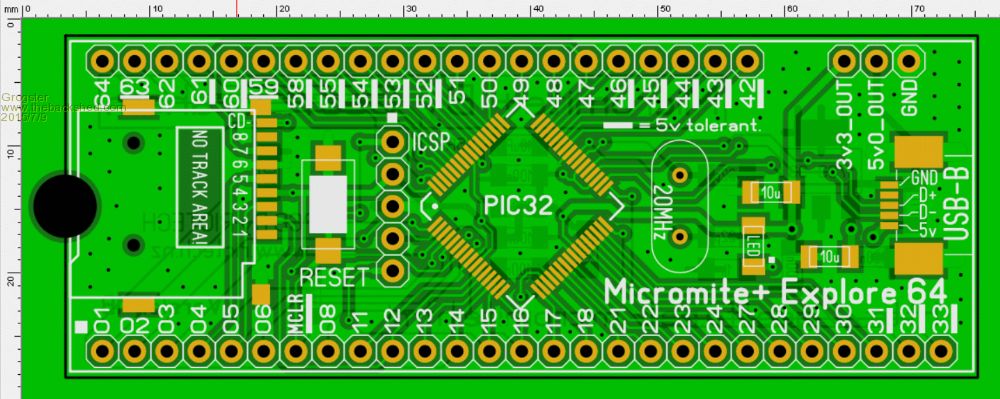
BOTTOM LAYER: 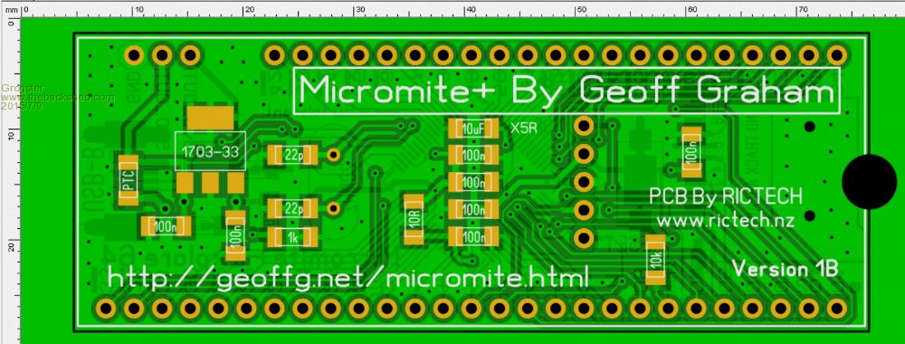
I currently have 150 of the 1B's in stock, BUT just the PCB at this stage. I will be offering complete kits as well as just the board on my website, which is due to launch by the end of July. However, to further the Beta testing phase, anyone here who is interested in building one or two for the next phase of the beta testing, just PM me, and I can arrange to send a board to you. Prices are: 1) US$15 for a panel of three boards, including airmail to anywhere on the planet 2) US$7.50 for one single PCB including airmail to anywhere on the planet. This is just the blank board, but I will be updating this thread very shortly with a BOM, so people who elect to get boards, can order in the components. All parts are standard - nothing non-standard or hard to find, so if you can't get the specific part on the BOM, you should be able to find another supplier easy enough. ...to be continued... Smoke makes things work. When the smoke gets out, it stops! |
||||
bigmik Guru Joined: 20/06/2011 Location: AustraliaPosts: 2981 |
Hi Grogs, Looks pretty cool, Is that a SD card socket at the end? What size SMD parts are they? Will 0805 fit there, I think they look bigger though,? What USB connector is it? Looks like a micro USB instead if a mini USB ..if a mini then maybe you should have allowed for more copper area to solder the connector too.. Usually minis have 4 solder points for the case mounting. Good looking PCB, keep up the good work. Regards, Mick Mick's uMite Stuff can be found >>> HERE (Kindly hosted by Dontronics) <<< |
||||
| Grogster Admin Group Joined: 31/12/2012 Location: New ZealandPosts: 9975 |
Hey buddy.
All parts are 1206. MicroSD card slot at left end(push-in/push-out type). Mini-USB "B" connector. 1:22AM - sleepy. Will catch ya all on the flip side..... 
EDIT: @ Mick - USB-B socket is a short type, not the long type. The short sockets only have two case mounting tabs, hence the two pads. Smoke makes things work. When the smoke gets out, it stops! |
||||
| Zonker Guru Joined: 18/08/2012 Location: United StatesPosts: 772 |
Nice board Grogs..! This is going to be an excellent edition to the MM line... A complete panel based computer..! Nice... Can't wait to start the beta testing on this one..! Thanks for, all your hard work on the PCB... Will be looking for the schematic and BOM...  |
||||
Lou Senior Member Joined: 01/02/2014 Location: United StatesPosts: 229 |
Great work Grogs, I will get with Zonker and we'll order some of your new play toys soon. Your Skinny Mite has been on my bench running non-stop for months. Thanks for all your hard work, Lou Microcontrollers - the other white meat |
||||
| Justplayin Guru Joined: 31/01/2014 Location: United StatesPosts: 330 |
Darn it!! I see the 470 is a new version. The new one is 120Mhz and the old one were 100Mhz. Now I'll have to order new 470 chips too.  
Oh well... Onward and upward! --Curtis I am not a Mad Scientist... It makes me happy inventing new ways to take over the world!! |
||||
| cdeagle Senior Member Joined: 22/06/2014 Location: United StatesPosts: 269 |
Very compact board Grog. I hope someone offers an assembled Micromite +. My soldering skills (and eyesight) are not what they used to be. |
||||
| WhiteWizzard Guru Joined: 05/04/2013 Location: United KingdomPosts: 2991 |
I will be selling fully assembled modules in about three weeks time on MicroMite.org 
However, if you can't wait that long, Grogster is selling PCBs now, and kits too (but obviously you need to get the soldering iron out to complete it). PM either Grogster or myself for more info 
|
||||
| cdeagle Senior Member Joined: 22/06/2014 Location: United StatesPosts: 269 |
Thanks Phil. |
||||
| Geoffg Guru Joined: 06/06/2011 Location: AustraliaPosts: 3362 |
The MM+ starts up at 100MHz so it will work with the old chips 100MHz chips. You can use CPU 120 to go faster if you have a 120MHz chip. Geoff Graham - http://geoffg.net |
||||
| Grogster Admin Group Joined: 31/12/2012 Location: New ZealandPosts: 9975 |
I have a couple of 120MHz 470's here, and I will be building a 1B board over the weekend with the 120, and I will be running tests on that one. 100MHz is plenty impressive enough though!
BOM and Schematic will be posted here, by the time those of you who have ordered PCB's have your boards, so watch this thread for updates in that department.
Smoke makes things work. When the smoke gets out, it stops! |
||||
TassyJim Guru Joined: 07/08/2011 Location: AustraliaPosts: 6538 |
Another big step forward for the 'mite series. A question about supplying external 5V. If you want to run the device of it's own supply and only plug a USB cable in occasionally, you would need a diode in the USB V+ line to prevent tying the two 5V sources together. Exactly where might depend on any future plans for the USB port. Jim VK7JH MMedit |
||||
| Grogster Admin Group Joined: 31/12/2012 Location: New ZealandPosts: 9975 |
Yes, excellent point Jim - Curses.... 
Oh well - I will put it on the list for the next PCB revision. The USB socket is Element14 part # 2300434. I chose this socket for a couple of reasons: (1) It had to be from a reliable source, (2) it had to be affordable(some Element14 prices are...odd) and (3) it needed to be the short one for space reasons. In hindsight, I could probably squeeze the more common longer socket in there, so I am looking at that for the next PCB revision, which would mean you can use any of the hundreds of cheap Chinese sockets on eBay, as well as from the likes of Altronics and Element14 etc. I have ten of those cheap eBay ones coming, and I will see about re-designing the footprint to accommodate the cheaper one or both. PCB's SENT TO THE FOLLOWING MEMBERS: - Lou - Zonker - Cherokeecruiser - Justplayin Smoke makes things work. When the smoke gets out, it stops! |
||||
| WhiteWizzard Guru Joined: 05/04/2013 Location: United KingdomPosts: 2991 |
Please only use these if you are not often inserting/removing the USB lead (or likewise an SD card with an SD socket). These cheaper eBay sockets will likely fail after a (short) while so I do not recommend using them in certain situations (but they are perfectly fine for 'playing' with to test things out). WW |
||||
| MicroBlocks Guru Joined: 12/05/2012 Location: ThailandPosts: 2209 |
Grogster, i have about 80 or so of the through hole version of the usb connector. Common part and good price.pm me if you are interested. Microblocks. Build with logic. |
||||
| Grogster Admin Group Joined: 31/12/2012 Location: New ZealandPosts: 9975 |
Good point. I think I will just wait and see what happens with respect to anyone managing to break off the USB socket - I would simply argue that you need to be more gentle!!!
The current one is only about 50c in American currency, so it's not that pricey, and it is from a reputable supplier. Smoke makes things work. When the smoke gets out, it stops! |
||||
| paceman Guru Joined: 07/10/2011 Location: AustraliaPosts: 1329 |
Grogs, just eyeballing it the pads for the 1206 devices don't seem to be extended in a bit to make the use of 0805's easier - is it possible to do this on the next version? Guess the 10K resistor pads on pin 7 would be a problem with the three tracks through but that seems to be the only one. Greg |
||||
f1fco Senior Member Joined: 18/03/2012 Location: FrancePosts: 155 |
is it a PCB for 100 pins PIC already available ? or in the (near) future ? Pierre 73s de F1FCO |
||||
| Geoffg Guru Joined: 06/06/2011 Location: AustraliaPosts: 3362 |
No, not yet. But if our plans work out there will be one in a few months. Geoff Geoff Graham - http://geoffg.net |
||||
| Grogster Admin Group Joined: 31/12/2012 Location: New ZealandPosts: 9975 |
I designed it for 1206. I know where you are coming from though, as you must have settled on 0805 series!!! 
I have settled on 1206 you see, and have heaps of that size in stock, and practically no 0805 - go figure!
I will have a look at that idea for the next run of boards, as apart from that 10k(and I can probably move it), that would allow you to use 1206 OR 0805 - more appealing to many, as MOST people seem to be 0805 or 1206 size in my experience. Smoke makes things work. When the smoke gets out, it stops! |
||||
| Page 1 of 8 |
|||||
| The Back Shed's forum code is written, and hosted, in Australia. | © JAQ Software 2026 |
