
|
|
Forum Index : Microcontroller and PC projects : MicroMite+ Explore64 PCB 1C...
| Page 1 of 5 |
|||||
| Author | Message | ||||
Grogster Admin Group Joined: 31/12/2012 Location: New ZealandPosts: 9975 |
This is the updated PCB for the MM+ module. TOP LAYER: 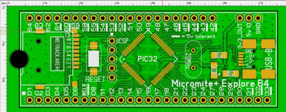
BOTTOM LAYER: 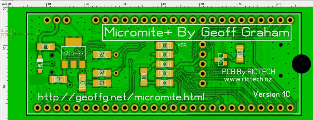
This revision of the board has the following improvements/changes: - 10k pullup to MCLR replaced with 130 supervisory IC on bottom layer Supervisory chip increases the unit price by about 50c, but this may well prevent any more of those hiccups that have been reported here with power-up flash corruption during the beta testing phase. - SOD123 Diode(1N5819) added in series with USB power to protect against external power This will block an external 5v supply from trying to go down the USB lead, if the USB cable and an external 5v supply are connected at the same time. Both the USB or external supply connection are via the PTC. - Mini USB-B socket swapped for a much more common footprint available just about anywhere The new footprint supports USB sockets that can be had from just about anywhere, rather then the special short one that has been used, which seems to only ba available from Element14. You now have more choice on where you get the USB socket from. - All 1206 SMD have 0805 overlayed on top, so people can choose either 1206 or 0805 components Most of the passive components are now dual-footprint, so that those who wanted to be able to use 0805 parts, can now do so. The board is still completely compatible with the 1206 size too, either size can now be used. I think this covers all the issues mentioned by beta testers thus far, yes? If anyone sees I have missed something previously discussed, please let me know. EDIT: Images not loading - not sure why - will try changing the filenames.... EDIT: Forum software does not like plus symbol in filename. Smoke makes things work. When the smoke gets out, it stops! |
||||
| WhiteWizzard Guru Joined: 05/04/2013 Location: United KingdomPosts: 2991 |
Hi G, Do you have protection between the reset switch and ICSP Pin1? In case the reset switch is pressed when flashing firmware I would add a 100R resistor between switch and ICSP Pin1 (to limit max current to a safe level). Other than this it is looking good 
WW |
||||
| Grogster Admin Group Joined: 31/12/2012 Location: New ZealandPosts: 9975 |
Good thinking. I've never heard of anyone doing that, but you obviously have? Smoke makes things work. When the smoke gets out, it stops! |
||||
| Chris Roper Senior Member Joined: 19/05/2015 Location: South AfricaPosts: 280 |
Microchip do it on most, if not all, of their demo boards they normally use 1K. Cheers Chris http://caroper.blogspot.com/ |
||||
| WhiteWizzard Guru Joined: 05/04/2013 Location: United KingdomPosts: 2991 |
I once had an issue with a 1K BUT this may have been a dry-joint. Anything between 100R and 4K7 should be fine in theory. Main point is that I would definitely add provision on the PCB for a resistor (if not too much trouble to add!) Maybe time for a 0603 
|
||||
| paceman Guru Joined: 07/10/2011 Location: AustraliaPosts: 1329 |
Grogs, many thanks for extending the pads to enable 0805 use - I think that'll help quite a few people. Greg |
||||
| Greg Fordyce Senior Member Joined: 16/09/2011 Location: United KingdomPosts: 153 |
How about adding a pad for a 10k pullup to MCLR? Then you have a choice of using either a simple resistor or the 130 supervisory ic. |
||||
| robert.rozee Guru Joined: 31/12/2012 Location: New ZealandPosts: 2528 |
would you mind posting a PDF of the schematic? i would like to see the pads for the 10k pullup on MCLR retained, in case someone chooses to not use the 130 supervisory IC. it may also be helpful for some constructors to up the size of the footprint for the 1N5819 considerably - there is space, so i'd suggest allowing for surface-mounting up to a regular leaded part, or at least overlaying a 1206 footprint as you have done with the resistors. addendum: looks like Greg Fordyce jumped ahead of me on the 10k pullup! i really shouldn't take so long composing my postings. cheers, rob :-) |
||||
| Grogster Admin Group Joined: 31/12/2012 Location: New ZealandPosts: 9975 |
@ Chris - OK. 
@ WW - OK. Will see if I can squeeze something in there. @ paceman - You are welcome. Several have asked for this - you were probably one of them!
@ Greg - Yeah, I did that on the Skinnymite(provision for either or), so that is a good idea. I think I have room for that. @ robert.rozee - Yep, good idea on the diode mod. Will do that too. Smoke makes things work. When the smoke gets out, it stops! |
||||
| Grogster Admin Group Joined: 31/12/2012 Location: New ZealandPosts: 9975 |
OK, I have made the changes. TOP LAYER: 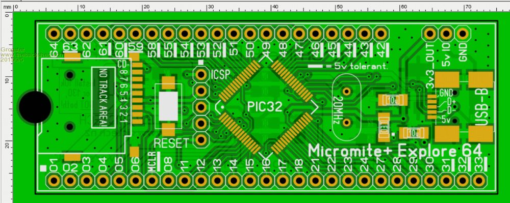
BOTTOM LAYER: 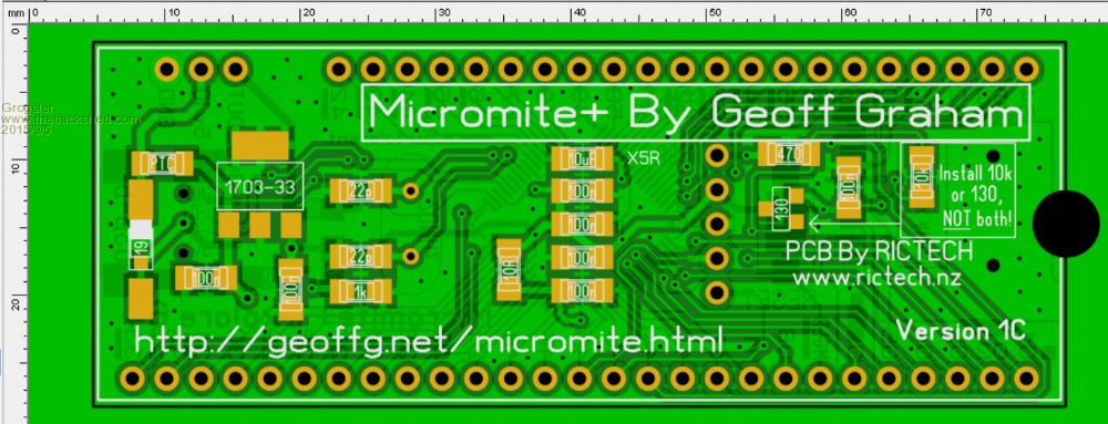
Additions: - Standard through-hole diode allowed for on USB. Surface mounted on bottom. Now you can use either a standard through-hole diode with legs bent, or a SOD123 SMD type. - 470R resistor between reset button and MCLR on ICSP. Both 0805 and 1206 footprint. - Choice of either the MCP130 or a standard 10k pullup for MCLR. 0805 and 1206 footprint. How we doin' now? (in any event, I am off to bed. ten past 3 in the morning - I must be freakin' mad......)Smoke makes things work. When the smoke gets out, it stops! |
||||
| WhiteWizzard Guru Joined: 05/04/2013 Location: United KingdomPosts: 2991 |
Hi G, Any chance of bringing all SMD pads in some more to allow for 0603's  |
||||
| MicroBlocks Guru Joined: 12/05/2012 Location: ThailandPosts: 2209 |
For the supervisory chip it is alsopossible to place a MCP120 AND a pullup resistor.  Can not get more versatile then that! Can not get more versatile then that!
I like the layout, not much to improve upon. Only for my personal selfish needs
0603 pad also as that is the format that i stock. I would like to see a jumper added to choose between USB and external power. I find that often the 5v from the USB is already lower. More around 4.5V and that is just barely enough to make a distance sensor or other 5v parts work reliably. A jumper would not lower that voltage more, a diode does. I looked at your PCB and i think it can be placed close to the power pins and USB. 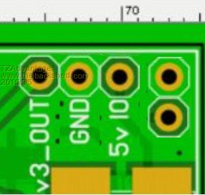
I realize that i could also just place a bridge instead of a diode but then it is more permanent and not suited for breadboard purposes. Microblocks. Build with logic. |
||||
TassyJim Guru Joined: 07/08/2011 Location: AustraliaPosts: 6538 |
Grogster, I think that Vbus needs to be changed to connect to the USB socket side of the diode. That seems to be the usual method but I am not sure if it makes any difference with the uMite firmware. If TZ's diode jumpers are placed with the USB 5V side of the diode placed in line with the other pins, it could be used as an external jumper. This makes the supply options more flexible without you having to do more of the decision making. Jim VK7JH MMedit |
||||
| Grogster Admin Group Joined: 31/12/2012 Location: New ZealandPosts: 9975 |
@ WW - 0603 should fit on the 0805 pads. By my measurements, the pad width is only 0.08mm narrower then that of the 0805 when overlapped, so I would expect that 0603 would fit fine on the 0805 footprint. I don't use any 0603. I note your smiley, but then TZA mentioned it too, so I figured I would check. @ TZA - The problem with the jumper, is that it would still be possible to have the jumper in place, AND have the external power connected, and we are then back to where we were before. The diode blocks any external juice from trying to go down the USB cable. I see what you are getting at, and I know about the diode voltage drop, but... @ Jim - GOOD CATCH! Absouletly correct. Vbus needs to be on the USB side - that is an error, so I will fix. That has come into play cos I added the diode, and forgot about Vbus. Thanks. 
Can you elaborate? I'm trying to picture what you mean, but I can't see it in my head. Smoke makes things work. When the smoke gets out, it stops! |
||||
| TassyJim Guru Joined: 07/08/2011 Location: AustraliaPosts: 6538 |
@Grogster, I know my ramblings would confuse, they confused me. TZ wants a jumper to short out the diode (to reduce voltage drop) If the jumper was placed as TZ indicated with one pin inline with the other pins, users would have three choices. 1. Leave the pins out and go with the diode. 2. Put the jumper pins on the top side to allow a jumper to be placed on as required. 3. Put one pin on the underside in line with the other power pins and let their external circuit make the connection as required. Option 3 with the diode left off allows all sorts of fancy power switching devices to be used. 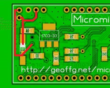
The pins could be labeled 5V USB, Gnd, 5V in, 3.3V out I think that TZ only wants to use the jumper to supply the full 5V to external devices. If so, only the one pin (in line with the existing pins) is required. Jim VK7JH MMedit |
||||
| Grogster Admin Group Joined: 31/12/2012 Location: New ZealandPosts: 9975 |
OK, thanks Jim, I understand that now.
I will make the changes. Smoke makes things work. When the smoke gets out, it stops! |
||||
| MicroBlocks Guru Joined: 12/05/2012 Location: ThailandPosts: 2209 |
This is what i did on my USB to serial module. 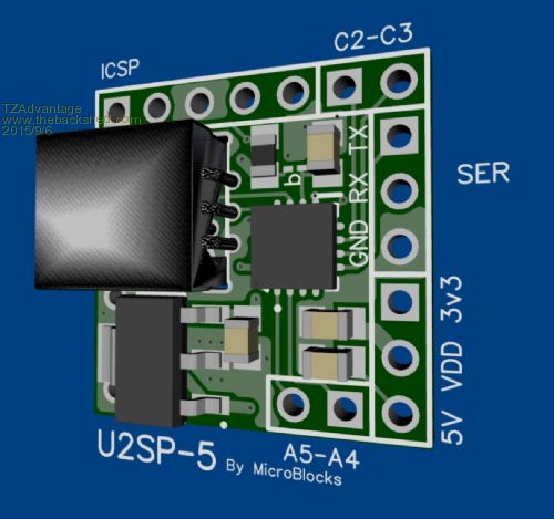
It also brings out the 5v from the USB and the 3.3v from the voltage regulator. The middle pin is called VDD and that supplies the PIC16F1455 with power. It can be used with a jumper, or an external circuit can make that connection. Errors can still be made. Can not stop that. When someone applies 5v to the 3v3 line it will cause problems too, so some responsibility has te be with the one who use it. Making it clear is our job, the rest...... Tassyjims suggestion is the most clear. You will have a 5v output and a 5v input. A jumper will in that case not be necessary as it can be on the external circuit. And just to make sure we mean the same i include the picture. 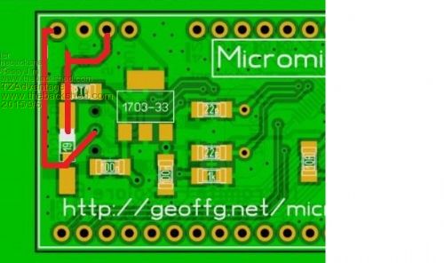
Microblocks. Build with logic. |
||||
| Grogster Admin Group Joined: 31/12/2012 Location: New ZealandPosts: 9975 |
UPDATE: TOP LAYER: 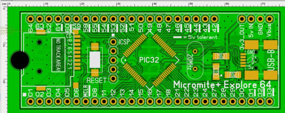
BOTTOM LAYER: 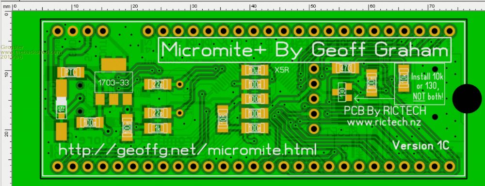
This should just about do it. Are we missing anything else? Smoke makes things work. When the smoke gets out, it stops! |
||||
| TassyJim Guru Joined: 07/08/2011 Location: AustraliaPosts: 6538 |
I think you have to consider the ability to program the chip with a supervisory chip in place. More b....dy jumpers. Jim VK7JH MMedit |
||||
| MicroBlocks Guru Joined: 12/05/2012 Location: ThailandPosts: 2209 |
This is just nitpicking so feelfree to ignore it.
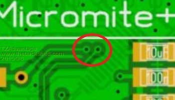
These two vias are very close together. When you move them away from each other a bit more then the ground planes will be connected a bit better. @TassyJim, As long as there is no capacitor from MCLR to GND then a Supervisory chip does not prevent the pickkit3 from working. Microblocks. Build with logic. |
||||
| Page 1 of 5 |
|||||
| The Back Shed's forum code is written, and hosted, in Australia. | © JAQ Software 2026 |
