
|
|
Forum Index : Microcontroller and PC projects : (mm) micromite 28pin rx / tx
| Page 1 of 2 |
|||||
| Author | Message | ||||
| B15HOP Newbie Joined: 11/09/2015 Location: AustraliaPosts: 15 |
I have a micromite 28 pin from here: http://geoffg.net/micromite.html The thing worked perfectly for first few trials. Using a serial connection to talk to it at 38400 baud and I was able to write some code etc... All of a sudden, the micromite decided not to communicate back to the rs232 chip. So even though the LED's light up, the chip seems not to be responding. Ironically the software that I had written in MMBasic still runs every time I fire up the chip. So basically the chip works but I can no longer talk to it. Is there a way to factory reset the chip or get it back to how it was before? Just so you know, I tested the rx/tx serial by looping back on itself. It works, so it's not the rx/tx serial board (sparkfun board). 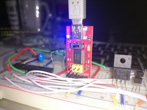
EDIT: Oh and I tried using the rx/tx short method to factory reset the pic32 and that didn't work either. |
||||
| atmega8 Guru Joined: 19/11/2013 Location: GermanyPosts: 738 |
Hello, of course there is a reset procedure. And this is described in detail in the *fu...* manual 😉 |
||||
| MicroBlocks Guru Joined: 12/05/2012 Location: ThailandPosts: 2209 |
Hi BI5HOP welkom to the forums! Please provide some more details. Like: Did you get the chip preprogrammed or you programmed it yourself. Do you know the software version? Do you have a pickit3 or have acces to one. Did you set a pincode. Is the capacitor at pins 19/20 good, is it a tantalum or X5R ceramic one? I have had problems with good contact before in a breadboard so i soldered the capacitor directly on the pins to get the best contact. Did you rewire anything before it went incommunicado? Double check the TX/RX on both sides just to make sure they have good contact. Maybe use different wires as a break in the wire could be possible. Microblocks. Build with logic. |
||||
Grogster Admin Group Joined: 31/12/2012 Location: New ZealandPosts: 9975 |
If the MM talks via loopback, and the 232 converter talks via loopback, then it must either be one or more of the wires, or the breadboard. Cheap breadboards have been a source of problems for many people - please use a good quality breadboard. 
Do you happen to have another breadboard you could test with? ...and as TZA said, welcome.  Smoke makes things work. When the smoke gets out, it stops! |
||||
| MicroBlocks Guru Joined: 12/05/2012 Location: ThailandPosts: 2209 |
I understood that the USB-Serial works with a loopback. The micro mite is not tested that way, it might be impossible to check. Maybe you can make a little indicator with a resistor and led to check if the signals reach the micromite. GND --- 330Ohm resistor ---- LED ----- pin test. Or if you have some equipment like a logic probe, logic analyzer or scope that would trace down the problem really quick. Microblocks. Build with logic. |
||||
TassyJim Guru Joined: 07/08/2011 Location: AustraliaPosts: 6538 |
It will help if we know what chip, MX150 or MX170 and what version of the firmware you have on it. The reset procedure may have changed over time but the manual you hopefully downloaded at the time you acquired the chip will be right for your firmware. You have tried the usual method (shorting Rx and Tx) but there may be others available. Other questions are How are you cannecting the Rx and Tx to the USB-TTL adapter What voltage is the TTL adapter Rx/Tx set to 3.3 or 5V If you are running the adapter at 5V and don't have a resistor in the Rx line, you may have damaged the chip but they are fairly robust. We have all become wary of breadboards. Jim VK7JH MMedit |
||||
| B15HOP Newbie Joined: 11/09/2015 Location: AustraliaPosts: 15 |
Hi TZ Advantage and thank you. :) Chip was preprogrammed with Micromite firmware mk2 4.6 (see pic from when it was working) 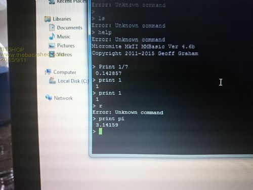
Don't have PicKit3 Never got to set a pincode Cap is a tantalum brand new and good. I unwired all the white wires you see in the first pic and then re connected Tx / Rx to make sure it wasn't those wires. I triple checked pin positions and still no luck. I'm suspecting the USB cable because when the machine boots, you can see the sparkfun try to send data but nothing comes my way. So possibly it could be the cable. Will try another cable soon. But then that wouldn't make sense because if i do a loop back on tx / rx I wouldn't see a reply huh? Edit: Cheers for all your help. Still baffled. Still won't reset for me either. |
||||
| B15HOP Newbie Joined: 11/09/2015 Location: AustraliaPosts: 15 |
Hey Jim Sparkfun is set to 3v3, it has a switch to set either 3v3 or 5v as you can see in the pic it's on 3v3. Connecting via breadboard but now i'm tempted to soldier to see if that fixes the issue. Tried shorting rx/tx but that doesn't do anything. |
||||
| sc05027 Newbie Joined: 01/01/2015 Location: Hong KongPosts: 10 |
have you tried swopping rx & tx? sc |
||||
| robert.rozee Guru Joined: 31/12/2012 Location: New ZealandPosts: 2528 |
do you have a multimeter that you can use to (a) check the supply voltage, and (b) measure the current consumption? the first thing to check is that the micromite chip is being supplied with about 3.3 volts and that it is consuming about 25mA. after confirming these numbers, you need to check with the multimeter on ohms range that all the ground pins are connected to ground, and that all the Vcc pins are connected to 3.3 volts. cheers, rob :-) |
||||
| B15HOP Newbie Joined: 11/09/2015 Location: AustraliaPosts: 15 |
voltages are 3.29 or there about. Checked the three neg and two Vcc. As I said the software I wrote still runs on boot (autorun) but I can no longer talk to it... |
||||
| WhiteWizzard Guru Joined: 05/04/2013 Location: United KingdomPosts: 2991 |
Hi BI5HOP, One other (often overlooked) thing for 'new comers' using a Windows environment, is the fact that if using TeraTerm and IF there is a loose cable between the PC and the USB module, then TeraTerm will no longer see the USB module (and hence the MicroMite). You have to re-establish the connection - many ways to do this but the easiest is to use the 'Disconnect' then 'New connection' (both under the 'File' tab). I have had many customers with 'cheap' USB cables causing this exact problem you are seeing. The other 'common' issue we see a lot of are 'cheap' breadboards. If you are able to solder the basic setup shown in the manual to a 28-pin DIP socket (just a few connections) then you can eliminate any breadboard issue. Do NOT just assume that a connection is made between two points by 'visually' looking at a wire plugged into the board (or an IC pin!). We have resolved many issues caused by 'open circuits' from poor quality breadboards. The 28-pin socket idea is a quick way to create a simple 'test' circuit - something I think you will find useful. And IF your PIC is blown for whatever reason, then when you get hold of another programmed PIC you can simply plug it into your already created 'test' circuit. If you don't have a 28-pin DIP available, then your next best move is as Rob has posted above, i.e. if you have a multimeter then do some thorough testing between device pins and power points. Make sure vCap (the tantalum) is connected with the correct polarity too (+ve to pin 20, -ve to Pin 19). I assume you have it correct but worth checking as this has caused people problems too. Good luck - and do let us know how you get on . . . . WW |
||||
| WhiteWizzard Guru Joined: 05/04/2013 Location: United KingdomPosts: 2991 |
Is it set to AUTORUN? If so, then have you pressed Ctrl-C to stop your program? Sorry if these sound silly to you - but we have to eliminate everything to resolve it!!!
I can be online for a while if you are able to respond now . . . |
||||
| B15HOP Newbie Joined: 11/09/2015 Location: AustraliaPosts: 15 |
I did this when testing the loopback of the sparkfun rs232 usb board. Well the rx & tx were set correctly initially thus the first screenshot when it booted a week ago. I did try swapping them around but obviously that doesn't work. |
||||
| MicroBlocks Guru Joined: 12/05/2012 Location: ThailandPosts: 2209 |
Just to add a bit about breadboards. The way you use the USB-Serial from Sparkfun is not the best for the breadboard. Standard header pins are too thick. This causes the breadboards internal metal rails to bend, causing pins right next to it to not make good contact. When removing the module often those metal rails do not spring back all the way, leaving a row with future connection problems. Try to buy wires that have a female connector on one side and a male pin on the other side. They are pretty cheap and allows you to use the module in a better position. Another thing about teraterm that is easy to overlook. Often the serial settings are lost between sessions. Make sure the baudrate setting is correct. Microblocks. Build with logic. |
||||
| B15HOP Newbie Joined: 11/09/2015 Location: AustraliaPosts: 15 |
You are my hero. I don't know why I never thought of doing that earlier. Especially since I knew it was like a bash terminal eg VT100. Argh all this stress for nothing :D I have a big smile now.  So happy. So happy. |
||||
| B15HOP Newbie Joined: 11/09/2015 Location: AustraliaPosts: 15 |
I tested serial plug and unplug and as you say, it stops communicating to the sparkfun board. Since the blue LED that lights up when I type on tera term lights up when there is activity from the keyboard. You are right that if I unplug and replug the connection is lost even though it doesn't appear so from the console. |
||||
| WhiteWizzard Guru Joined: 05/04/2013 Location: United KingdomPosts: 2991 |
Excellent - but do take note of 'potential' issues with all that has been mentioned in the posts here. It is worth getting a 'soldered' set-up as this will save potential 'headaches' caused by various things. Invest in a 28-pin socket and solder some caps and resistors as required. Alternatively something like BigMiks MuP PCB is an excellent starting point for the 28-pin MM. Anyway, great news you're up and running again . . . Have FUN! WW |
||||
| MicroBlocks Guru Joined: 12/05/2012 Location: ThailandPosts: 2209 |
Ha, makes me smile too. I guess we all go through the same steps :) Microblocks. Build with logic. |
||||
| WhiteWizzard Guru Joined: 05/04/2013 Location: United KingdomPosts: 2991 |
@ B15HOP Just to make you feel better, I have to confess that I still make what some people will see as 'basic' mistakes such as this. Considering that I have been playing with MicroMites since the very early testing days you would think that I should know better by now! I am sure there are other every-day users here too that still make the odd silly mistake (aren't there!!  ) ) |
||||
| Page 1 of 2 |
|||||
| The Back Shed's forum code is written, and hosted, in Australia. | © JAQ Software 2026 |
