
|
|
Forum Index : Microcontroller and PC projects : Free pic16f1455 USB/Serial PIC32 prgmer
| Author | Message | ||||
| MicroBlocks Guru Joined: 12/05/2012 Location: ThailandPosts: 2209 |
You need to add a voltage regulator to get 3.3v or use an existing power supply. In the schematic i use 3.3v as it can also be used as a programmer for PIC32 chips, and they are 3.3v. The USB is only connected with GND, D+ and D-. The VUSB is NOT connected. You can use VUSB (pin 1 on the USB connector) as the input to a 3.3v voltage regulator as this will also add protection action overcurrent. The resistor, diodes and LED's are dimensioned for use with 3.3v. Microblocks. Build with logic. |
||||
| MicroBlocks Guru Joined: 12/05/2012 Location: ThailandPosts: 2209 |
I got a message that one of the padded envelopes arrived. So i bump this thread to invite people who receive it to use this thread to test the device. I would suggest to get at least a 3.3v regulated voltage available and some wires to solder to the mini USB connector. Test the LEDs part of the circuit first and simulate a low/high/disconnected state by using a wire to connect the resistor first to GND, then +3.3v and also unconnected. You would expect only one of the leds to be on when connected to GND and the other led when connected to the +3.3v and no leds on when not connected. The fourth 'state' is only possible with the microcontroller because the program will change the RC2 pin very rapidly between a '0' and a '1' to visually make both leds on. Hope that more of them will arrive soon. Microblocks. Build with logic. |
||||
Grogster Admin Group Joined: 31/12/2012 Location: New ZealandPosts: 9584 |
Mine arrived today.  Smoke makes things work. When the smoke gets out, it stops! |
||||
| MicroBlocks Guru Joined: 12/05/2012 Location: ThailandPosts: 2209 |
Good. I have some more enhancements in the works. Like the mode button acting like a reset button for a connected MCU. (Pressing the button for 4 seconds). To preserve power switch of the leds after a few seconds and when the button is pressed shortly show the mode it is in. Also, but this will take a while, an I2C tester. This would then allow to test (also in-circuit) I2C chips. I would really like a I2C monitor by capturing all traffic but that seems not possible...yet. Microblocks. Build with logic. |
||||
| viscomjim Guru Joined: 08/01/2014 Location: United StatesPosts: 925 |
This is a very cool project. Thanks MB. I might have to try this out. |
||||
| MicroBlocks Guru Joined: 12/05/2012 Location: ThailandPosts: 2209 |
I received some more confirmations about people receiving the parts. Please use this thread for questions and feedback. Microblocks. Build with logic. |
||||
| twofingers Guru Joined: 02/06/2014 Location: GermanyPosts: 1566 |
Hi MB, out of curiosity: why do you use two diodes 1N4148 in your schematic? AFAIK are they not necessary. Regards Michael causality ≠ correlation ≠ coincidence |
||||
| MicroBlocks Guru Joined: 12/05/2012 Location: ThailandPosts: 2209 |
Hi Michael, The two diodes drop the voltage over the LED's. Without them both leds will light up when the output pin is made an input (high impedance). With the diodes both LED's will be off in that case or depending on the efficiency of the LED's glow very dimly. This way i can signal 4 different states with only one microcontroller pin. The four states are: Both LEDs off, LED 1 on, LED2 on and both LEDs on. Both Leds on is done by changing the output pin very rapidly between '0' and '1'. Microblocks. Build with logic. |
||||
| twofingers Guru Joined: 02/06/2014 Location: GermanyPosts: 1566 |
yes, they should reduce the voltage 2x 0.7v volts down. Thanks, seems it wa too early! But it looks like a trick, not very conventional ... 
I'm soldering again ... Michael causality ≠ correlation ≠ coincidence |
||||
| MicroBlocks Guru Joined: 12/05/2012 Location: ThailandPosts: 2209 |
A windows XP driver: 2015-12-08_115027_Microblocks_USB_Serial_Driver.zip Microblocks. Build with logic. |
||||
| paceman Guru Joined: 07/10/2011 Location: AustraliaPosts: 1329 |
Thanks for the XP driver Jean, I've tried the 1455 and your software out now using my old XP system on PeterM's Micromite+ "Ultimate" backpack (V1.1) with the 64 pin MX470 - and it works a treat, very straight forward. It took me a while to remember how to use the MS command window (to run 'pic32prog' in) but once I'd sorted that out (with a bit of help from friends ) it was simple. I used the command Rob Rozee specified in his pic32prog thread, i.e.
pic32prog -d ascii:com12 Micromite_Plus_V4.7B37.hex So, one press of the 'Mode' change switch on Peter's board, mode goes from USB CONSOLE (red LED) to PROGRAM (green LED), hit Return on the old laptop and two minutes later a re-programmed 470 (I know, I know - time I upgraded and then it would be just 30secs). Take a bow all involved, Jean, Robert, Peter, Serge and of course Geoff. Greg BTW - how did everyone else go with their systems testing Jean's 1455 program. I haven't seen any further posts? C:\Documents and Settings\Greg Yaxley>cd desktop/pic32prog
C:\Documents and Settings\Greg Yaxley\Desktop\Pic32Prog>pic32prog -d ascii:com12 Micromite_Plus_V4.7B37.hex Programmer for Microchip PIC32 microcontrollers, Version 2.0.186 Copyright: (C) 2011-2015 Serge Vakulenko (ascii ICSP coded by Robert Rozee) Adapter: . OK1 OK2 - ascii ICSP v1E Processor: MX470F512H Flash memory: 512 kbytes Boot memory: 12 kbytes Data: 494772 bytes Erase: (80mS) done Loading PE: 1 2 3 4 (LDR) 5 6 7a (PE) 7b 8 v0201 Program flash: ################################################ done Program boot: ######### done Verify flash: ################################################ done Verify boot: ######### done Program rate: 3802 bytes per second total TDI/TMS pairs sent = 4342610 pairs total TDO bits received = 176944 bits total ascii codes sent = 1291625 total ascii codes recv = 60847 maximum continuous write = 452 chars O/S serial writes = 120795 O/S serial reads (data) = 5537 O/S serial reads (sync) = 2344 XferFastData count = 103873 10mS delays (E/X/R) = 8/0/0 elapsed programming time = 2m 13s C:\Documents and Settings\Greg Yaxley\Desktop\Pic32Prog> |
||||
| robert.rozee Guru Joined: 31/12/2012 Location: New ZealandPosts: 2428 |
is excellent to hear that an MX470 has been programmed successfully using pic32prog! cheers, rob :-) |
||||
| twofingers Guru Joined: 02/06/2014 Location: GermanyPosts: 1566 |
Hi Jean, 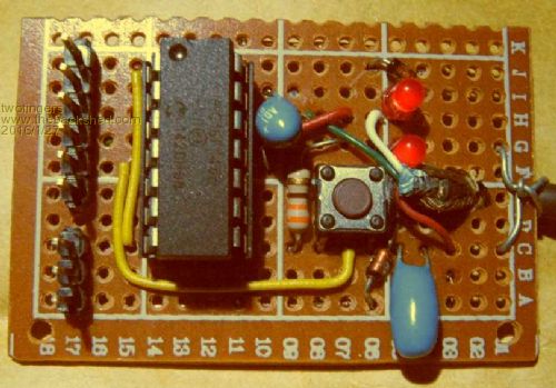
in the meantime (actually since october) I have my/(your) 1455-Programmer ready (WinXP). 
I did not try the pic32prog with it yet. 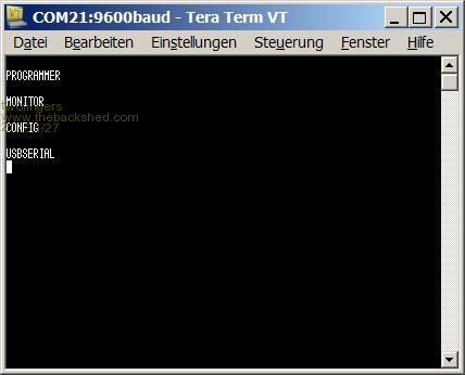
But maybe I need some more informations, please. Can I download a manual for this and a USB-driver for Win7? If not, how can I use the MONITOR and CONFIG mode (maybe this are dummys only)? The baud rate control has to make at the driver window? Regards Michael causality ≠ correlation ≠ coincidence |
||||
| MicroBlocks Guru Joined: 12/05/2012 Location: ThailandPosts: 2209 |
The XP driver i posted here also works fine in windows 7. Only two modes are active. USBSERIAL and PROGRAMMER. The other two were placeholders for future extensions. It will be the easiest to use when you know which LED is on in what mode, then you don't need a terminal to know in what mode it is. It will always startup in USBSERIAL mode. When programming a baudrate is not necessary as it will be using the USB port directly. In USBSERIAL mode you can change the baudrate in your terminal. For the MicroMite you should use 38400. If you put it in PROGRAMMER mode you can then use pic32prog [code] pic32prog -d ascii:com21 Micromite.hex [/code] Make sure you are in the pic32prog directory otherwise the command will not be found. Also make sure you use the right com port and hex file. Check above post of paceman to see how the output should look like. Did you use it as a USBSERIAL? How are your findings? Microblocks. Build with logic. |
||||
| twofingers Guru Joined: 02/06/2014 Location: GermanyPosts: 1566 |
Thanks Jean!
Yes, the XP driver also works fine in windows 7/64 (got a installer warning/ignored). I tried the usb-serial mode. Works very well, but maybe you should mention, do not use more than 128000 baud! Or change the code to ignore baudrate settings above 128000? The programmer testing follows. Regards Michael causality ≠ correlation ≠ coincidence |
||||
| MicroBlocks Guru Joined: 12/05/2012 Location: ThailandPosts: 2209 |
I have tested until 512000 and it worked ok, but this was a mcu and the pic sitting close to eachother on a pcb. It might be that the mcu is not keeping up which is very likely. Also things like cable length/quality becomes an issue. A simple uart with a RX/TX is not the best way to go faster. A differential solution, that is what USB is would be better. Keep the wires short and if you need more length make the USB cable longer. Microblocks. Build with logic. |
||||
| twofingers Guru Joined: 02/06/2014 Location: GermanyPosts: 1566 |
Uhh, I did not expect that. here is a screenshot from my USB driver propertys window (Win7/64). 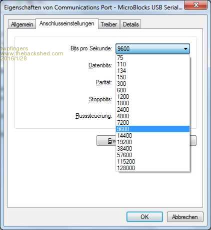
Serial wires are 200mm, USB cable is > 1500mm (soldered to the PCB). This is what happens (starting at 115200 Baud): 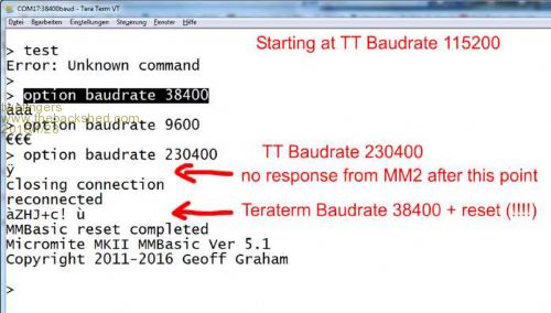
Please note, I'm not unhappy with 115200 Baud. It is just something you have to know. Michael causality ≠ correlation ≠ coincidence |
||||
| MicroBlocks Guru Joined: 12/05/2012 Location: ThailandPosts: 2209 |
The 512k was not with a Micromite but with another pic with my own code. I will test it again with a MicroMite soon. I did test it until 115200, i was under the impression that was the highest one supported on the Micromite, but i just checked the manual again and indeed it should be able to go higher. It does get more critical at higher speeds and without a crystal on the USB/Serial it might get tricky. Microblocks. Build with logic. |
||||
| matherp Guru Joined: 11/12/2012 Location: United KingdomPosts: 10180 |
I can confirm the Micromite console doesn't work at 230400 baud (at least on any variant of USB adapter I've tried). |
||||
| twofingers Guru Joined: 02/06/2014 Location: GermanyPosts: 1566 |
Hi Peter, ??? I'm not sure if I understand you right. I've used my MMs many times at 230400 baud with my cheap CP2102 USB-serial adapters. Regards Michael 
causality ≠ correlation ≠ coincidence |
||||
| The Back Shed's forum code is written, and hosted, in Australia. | © JAQ Software 2025 |
