
|
|
Forum Index : Microcontroller and PC projects : [MMBasic][MM2] MM.DSO a code example
| Author | Message | ||||
| twofingers Guru Joined: 02/06/2014 Location: GermanyPosts: 1761 |
MM.DSO a simple Digital Storage Oscilloscope 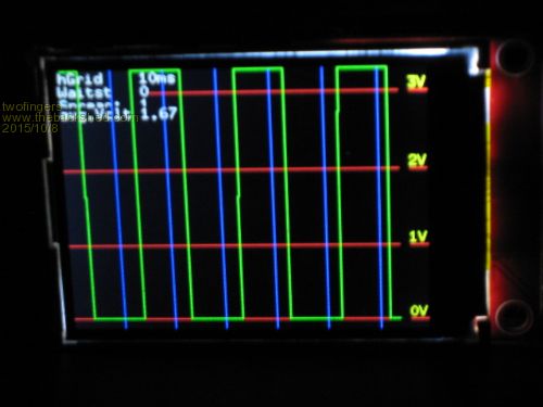
This picture shows the output for 50Hz/50% (~100 samples/cyle). For this demo I conected the Input pin(23) with output (PWM) pin(26). A voltage divider (1/10) seems a good idea. '*******************************************************
' MM.DSO a simple Digital Storage Oscilloscope (kind of) ' this is a quick & dirty Version 0.09 beta ' tested for frequencies from 1 to 100 Hz (or more) ' ' System: MMBasic 4.7 Micromite 2 ' (MX170/28, Micks BP170 + 2.4" TFT 240x320) ' by twofingers 10-2015 at TBS ' ' Used keys (serial): ' TAB switches gain (3V/30V) vertical res. ' I enable/disable info text ' 1-4 Spread increase/decrease vertical ' +- Waitstates increase/decrease ' >< increase/decrease hor. grid ' q quits ' ' Used PINs (MX170/28): ' 23 as Input ' 26 as Output for Demosignals (PWM, SERVO or DOUT) '******************************************************* ' This code may be freely distributed and changed. ' Provided AS IS without any warranty. ' Use it at your own risk. All information is provided for ' educational purposes only! ' ------------------------------------------------------ ' ++++++ Credit to Geoff for his great MMBasic ++++++ '******************************************************* Option explicit CPU 48 Const border_r=25 ' voltage scala Const screenwidth=MM.HRes-border_r ' usable screenwidth Dim float p(screenwidth),y,y0,F,tm,w,x_base,vsum,VCorrect=1 'float is faster than int Dim integer i, x=0 'x=hor_pos Dim integer baseline, waitstates, gain=70,level=0,hGrid=10, Info=1 On KEY Keyhandler Colour RGB(GREEN), RGB(BLACK) CLS SetPin 23,AIN 'Input '************* Demo Signals ************** 'SetPin 26,DOUT 'Output signal generator 'SetTick 1000,SigGen ' or PWM 2,50,50 ' or 'Servo 2,18 '****************************************** baseline=MM.VRes-10 F=1 'hor spread default = 1 waitstates=0: 'slow sample speed down, default = 0 SetupScreen y0=baseline Do If x=0 Then If waitstates Then ' To be as fast as possible, we use 2 Sample Loops tm=Timer For i = 1 To screenwidth:p(i)=Pin(23):wait:Next Else tm=Timer For i = 1 To screenwidth:p(i)=Pin(23):Next EndIf tm=Timer-tm 'Print tm:End x_base=screenwidth/tm '4,6s/ms Box 0, 0,screenwidth, MM.VRes, 0,0,0 'CLS SetupScreen For i = Hgrid*F To tm Step Hgrid*F ' 10=1/100sec = 1000ms/10 Line x_base*i, 0,x_base*i, MM.VRes, , RGB(blue) Next i vsum=0:For i = 1 To screenwidth:vsum=vsum+p(i) :Next 'For i = 1 To screenwidth: Print p(i):Next EndIf x=x+1 If (x+border_r)*F>=MM.HRes*F Then 'new screen Pause 400 x=0 EndIf y=baseline-p(x/F)*gain If x>1 Then Line x,y0,x,y y0=y Loop Sub SigGen 'settick interrupt If level = 0 Then level = 1 Else level = 0 Pin(26)=level End Sub Sub SetupScreen Local scalefactor=70 Local integer sc0=MM.VRes-baseline, sc1=sc0+scalefactor Local integer sc2=sc0+scalefactor*2,sc3=sc0+scalefactor*3 Local string volt(4,1) = (""," 0V"," 1V"," 2V "," 3V",""," 0V","10V","20V","30V") LENGTH 3 Local integer g=(gain=7) Line 0, MM.VRes-sc0,MM.HRes, MM.VRes-sc0, , RGB(red) '0V line Line 0, MM.VRes-sc1,MM.HRes, MM.VRes-sc1, , RGB(red) ' Line 0, MM.VRes-sc2,MM.HRes, MM.VRes-sc2, , RGB(red) ' Line 0, MM.VRes-sc3,MM.HRes, MM.VRes-sc3, , RGB(red) '3/30V line Text MM.HRes-border_r, MM.VRes-sc0-13, volt(1,g), , 2,1,RGB(YELLOW) Text MM.HRes-border_r, MM.VRes-sc1-13, volt(2,g), , 2,1,RGB(YELLOW) Text MM.HRes-border_r, MM.VRes-sc2-13, volt(3,g), , 2,1,RGB(YELLOW) Text MM.HRes-border_r, MM.VRes-sc3-13, volt(4,g), , 2,1,RGB(YELLOW) If Info Then Text 0,0, "hGrid "+Str$(Hgrid)+"ms", , 2,1,RGB(WHITE) Text 0,12, "Waitst "+Str$(Waitstates), , 2,1,RGB(WHITE) Text 0,24, "Spread: "+Str$(F), , 2,1,RGB(WHITE) Text 0,32, "avg.Volt"+Str$(vsum/screenwidth,2,2), , 2,1,RGB(WHITE) EndIf End Sub Sub wait For w=1 To waitstates:Next End Sub Sub keyhandler 'kbd interrupt handler Local key$ key$=Inkey$ Do While Inkey$=" ":Loop Select Case key$ Case "1" To "4" F=Val(key$) Case "I","i" Info=Not Info Case "+" If Waitstates=0 Then Waitstates=1 Else If Waitstates<10000 Then Waitstates=Waitstates*10 EndIf Case "-" If Waitstates=1 Then Waitstates=0 Else If Waitstates>0 Then Waitstates=Waitstates/10 EndIf Case ">" If Hgrid<10000 Then Hgrid=Hgrid*10 Case "<" If Hgrid>10 Then Hgrid=Hgrid/10 Case Chr$(9) If gain = 70 Then gain=7 Else gain=70 EndIf Case "q" end End Select End Sub End This is useful to inspect servo and/or slow PWM signals. One sample cycle (295 samples) takes ~64ms. I guess a CFunction could improve the sample speed by a factor of 10-20x. e.g. long long readADCtoArray(float array[], long long *elements, long long *delay, long long *pin)
{} could then replace this For i = 1 To screenwidth:p(i)=Pin(23):wait:Next i
Maybe a touch control can be done. We will see ... Strange: It seems the 48Mhz MM2 is much faster than the 80Mhz Maximite. Floats are faster than integers. Please note: this is still an incomplete code sample! It needs more testings and some updates. Download: 2015-10-08_230607_MMDSO009.zip Regards Michael causality ≠ correlation ≠ coincidence |
||||
| isochronic Guru Joined: 21/01/2012 Location: AustraliaPosts: 689 |
Any chance of connecting it to a 50 or 100 hz sin (eg plugpack) wave ? There was some discussion of noise a while back, I have not had problems myself but it should show with a sin waveform better than a rail on/off value. If ten or so measurements or so are needed each value, that would allow ten or so values a cycle in the above image and the square wave should be a little rounded off...? (ed) BTW The spec for the A/D is one million samples/sec, even scoping it down a bit for day-to-day practicality it is good for a few hundred ks/sec at least. I would prefer the 12-bitter but, I don't think USB connections and quiet A/Ds work too well though. |
||||
| twofingers Guru Joined: 02/06/2014 Location: GermanyPosts: 1761 |
Sure! I connected two MM2's. The first with Peters function generator. The second with my "DSO" code (both MMBasic 4.7/b32). I can get about 5000s/sec in pure Basic. 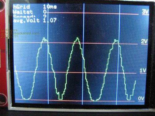
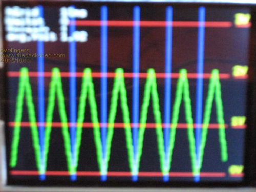
This is an unfiltered sine wave (Spread=2). And here comes a 100Hz triangel wave (Spread=1). i%=funcgen(9,100,"Triangle"
why? Here are the original sample values for the first picture (50hz/50%PWM) 2015-10-11_152442_rect_samples.zip Bugfix: Download: 2015-10-11_202438_MMDSO010.zip Regards Michael causality ≠ correlation ≠ coincidence |
||||
| isochronic Guru Joined: 21/01/2012 Location: AustraliaPosts: 689 |
I thought, to get a value in MMBasic, that ten samples had to be taken, and then the two extremes were discarded and the rest averaged ? From 5000 s/sec that would yield about 500 values/sec, which would mean about ten per 50hz waveform , so a square wave should be a little rounded. (?) (I think it looks pretty nifty anyway !) |
||||
| twofingers Guru Joined: 02/06/2014 Location: GermanyPosts: 1761 |
AFAIK this does Geoff (in his MMBasic) already for us, like Peter (MatherP) somewhere (PID) has explained (14 ADC reading, discarding the two extremes?). Thats why I think a CFunction could speed up the ADC readings (and storing) by 10-20 times. EDIT: causality ≠ correlation ≠ coincidence |
||||
| isochronic Guru Joined: 21/01/2012 Location: AustraliaPosts: 689 |
That clears it up, thanks. I think the method of discarding samples is kind of fishy though. |
||||
| twofingers Guru Joined: 02/06/2014 Location: GermanyPosts: 1761 |
I can not agree. IMHO is it a very intelligent (and often used) solution if you can take enough samples. I think for this little project is a reduced accuracy sufficient. EDIT Just out of curiosity. This shows a 500hz triangle wave to give an impression about 10s/cycles. Very bad. 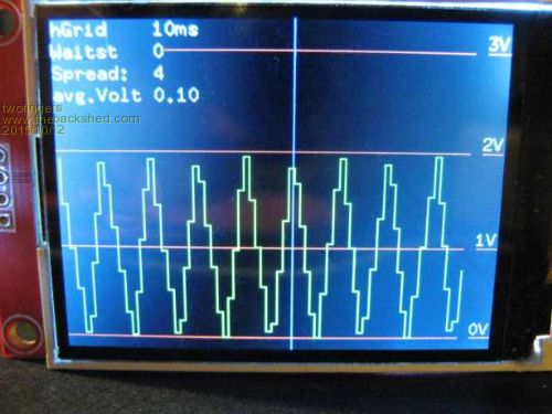
EDIT2: 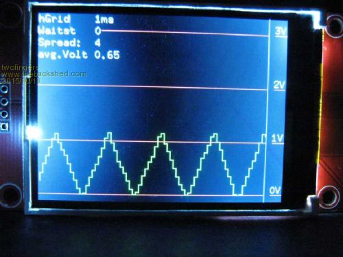
This picture - created by the newest MM.DSO version (incl. CFunction) and a voltage divider - shows a 5000Hz triangle wave signal (>80000s/sec). WOW!  causality ≠ correlation ≠ coincidence |
||||
| twofingers Guru Joined: 02/06/2014 Location: GermanyPosts: 1761 |
Today Peter (M.) released his very powerful MM+: 1.8Msps dual channel oscilloscope. That reminded me of my MM.DSO for uM2 (80Ks/s). Although it's still unfinished: Download: 2015-10-25_190706_MM.Ossi48.zip '*******************************************************
' MM.DSO a simple Digital Storage Osclloscope (kind of) ' this is a quick & dirty Version 0.48 beta (with CFunc) ' for frequencies from 1 to 5KHz (or more) ' ' System: MMBasic 4.7 (b32) ' Micromite 2 (MX170/28, Micks BP170 + 2.4" TFT) ' by twofingers 10-2015 at TBS ' ' Used keys (serial): ' TAB switches gain (3V/30V) vertical res. ' I enable/disable info text ' 1-5 Spread increase/decrease vertical ' +- Waitstates increase/decrease ' >< increase/decrease hor. grid ' " " <Space> = idle mode on/off ' a Autogrid mode on/off ' s print samples (serial) raw data! ' q quits ' ' Used PINs (MX170/28): ' 23 as Input ' 26 as Output (for Demosignals) ' ' LIMITS: max. input 3.3V, ~5KHz, positive voltage only! ' The "Ticks" are not as exact as they should. ' '******************************************************* ' This code may be freely distributed and changed. ' Provided AS IS without any warranty. ' Use it at your own risk. All information is provided for ' educational purposes only! ' ------------------------------------------------------ ' ++++++ Credit to Geoff for his great MMBasic ++++++ ' also Peter C.(G8JCF), Peter M. and TassyJim ' for the excellent CFunction support '******************************************************* 'Command line settings 'OPTION LCDPANEL ILI9341, L, 4, 5, 6 'OPTION TOUCH 7, 2 'GUI TEST TOUCH 'GUI CALIBRATE Option explicit CPU 48 ' CPUspeed=48, 1 tick=41,667ns, 1ms/41,667ns=24000 Const prg_version=0.48 Const TicksPerMS=24000 Const BORDER_R=25 ' voltage scala Const baseline=MM.VRes-10 Const screenwidth=MM.HRes-border_r ' usable screenwidth Const buffer_mult=1, BUFFERSIZE=buffer_mult*screenwidth Const FALSE=0, TRUE=1 Const LOW=0, HIGH=1 Const INPUT_PIN=23 Const cc=1.15 ' "cosmological constant" ;-)) (to cheat with ticks) Const hmax=11 Dim integer ticks, h=1 Dim integer p(BUFFERSIZE) 'buffer for samples Dim integer y,y0 'y=vert_pos Dim float hg(hmax)=(0,0.1,0.2,0.5,1,2,5,10,20,50,100,200) Dim float tm ' time to sample 295 values Dim float SamplesPerMS Dim float VSum=0, VCorr=33.5 ' modify for voltage divider Dim float Hgrid=hg(h) ' Dim float i ' general counter Dim integer F=1 'hor spread 1-5, default = 1 Dim integer x=0 'x=hor_pos Dim integer waitstates=1 'slowing sample rate, default = 1 Const sampletime=250 Dim integer s_delay Dim integer gain=70, level=LOW, Info=TRUE, IDLEmode=FALSE Dim integer autogrid=TRUE, PrintSamples=FALSE Dim string msg$ On KEY Keyhandler SetPin INPUT_PIN,AIN 'Input '********** Demo Signals on PIN26 ********* ' just connect PIN 26 to INPUT_PIN (23) 'SetPin 26,DOUT 'Output signal generator 'SetTick 20,SigGen ' or 'PWM 2,50,50 ' or 'Servo 2,18 '****************************************** Titel_Screen Colour RGB(GREEN), RGB(BLACK) CLS SetupScreen Do '************** begin main loop ********************* If x=0 Then s_delay=waitstates*sampletime ' SetTick 0,SigGen ' for slow test signal on PIN 26 ' Timer=0 ticks=readADCtoArray(INPUT_PIN,p(),buffersize,s_delay) ' tm=Timer ' workaround (s. CFunction readADCtoArray) If waitstates=1 Then ticks=ticks*cc Else ticks=ticks*1.025 ' CPUspeed=48, 1 tick=41,667ns, 1msec/41,667ns=24.000 tm=ticks/TicksPerMS/buffer_mult ' SetTick 1000,SigGen ' for slow test signal on PIN 26 SamplesPerMS=(screenwidth+1)/tm '~80s/ms with CFUNCTION Print SamplesPerMS;" SamplesPerMS" Box 0, 0,screenwidth+1, MM.VRes, 0,0,0 'CLS SetupScreen If autogrid Then Do If tm/Hgrid*F >10 And h < hmax Then h=h+1: Hgrid=hg(h) If tm/Hgrid*F <2 And h > 1 Then h=h-1: Hgrid=hg(h) Loop While tm/Hgrid*F >10 Or tm/Hgrid*F <1 EndIf i = Hgrid*F If SamplesPerMS*i>screenwidth And h>1 Then h=h-1 Do While SamplesPerMS*i<screenwidth Line SamplesPerMS*i, 0,SamplesPerMS*i, MM.VRes, , RGB(BLUE) i=i+Hgrid*F Loop vsum=0:For i = 1 To screenwidth:vsum=vsum+p(i):Next vsum=vsum/VCorr y0=baseline-p(1/F)*gain/VCorr If PrintSamples Then On KEY 0 Print SamplesPerMS For i = 1 To screenwidth:Print i,p(i),p(i)*VCorr:Next i PrintSamples=FALSE On KEY Keyhandler EndIf EndIf x=x+1 If (x+border_r)*F>=(MM.HRes*F) Then 'new screen Pause 500 x=0 Do:Loop While IDLEmode EndIf y=baseline-p(x/F)*gain/vCorr If x>1 Then Line x,y0,x,y y0=y Loop '**************** main loop ************************ End Sub SigGen 'settick interrupt (Test signal) level = Not level:Print level Pin(26)=level End Sub Sub SetupScreen Local scalefactor=70 Local integer sc0=MM.VRes-baseline, sc1=sc0+scalefactor Local integer sc2=sc0+scalefactor*2,sc3=sc0+scalefactor*3 Local string volt(4,1) = (""," 0V"," 1V"," 2V "," 3V",""," 0V","10V","20V","30V") LENGTH 3 Local integer g=(gain=7) Local integer AG_Color If autogrid Then AG_Color=RGB(YELLOW) Else AG_Color=RGB(WHITE) Line 0, MM.VRes-sc0,MM.HRes, MM.VRes-sc0, , RGB(red) '0V line Line 0, MM.VRes-sc1,MM.HRes, MM.VRes-sc1, , RGB(red) ' Line 0, MM.VRes-sc2,MM.HRes, MM.VRes-sc2, , RGB(red) ' Line 0, MM.VRes-sc3,MM.HRes, MM.VRes-sc3, , RGB(red) '3/30V line Text MM.HRes-border_r, MM.VRes-sc0-13, volt(1,g), , 2,1,RGB(YELLOW) Text MM.HRes-border_r, MM.VRes-sc1-13, volt(2,g), , 2,1,RGB(YELLOW) Text MM.HRes-border_r, MM.VRes-sc2-13, volt(3,g), , 2,1,RGB(YELLOW) Text MM.HRes-border_r, MM.VRes-sc3-13, volt(4,g), , 2,1,RGB(YELLOW) If Info Then Msg$=Str$(Hgrid)+"ms/"+Str$(1000/Hgrid)+"Hz/div" Text 0,0, ">< hGrid "+Msg$, ,2,1,AG_Color Text 0,15, "+-Waitst "+Str$(Waitstates)+" ms:"+Str$(tm,2,0), , 2,1,RGB(WHITE) Text 0,30, "Spread: "+Str$(F), , 2,1,RGB(WHITE) Text 0,45, "avg. Volt"+Str$(vsum/screenwidth,2,2), , 2,1,RGB(WHITE) EndIf End Sub Sub Titel_Screen Colour RGB(GREEN), RGB(BLUE) CLS Text MM.HRes/2,30, "** MM.DSO **", CM, 2,3,RGB(YELLOW) Text MM.HRes/2,70, "Version:"+Str$(prg_version,2,2), CM, 2,2,RGB(WHITE) Text MM.HRes/2,120, "Input pin: "+Str$(INPUT_PIN),CM , 2,2,RGB(WHITE) Pause 1000 End Sub Sub keyhandler 'kbd interrupt handler On key 0 Local key$ key$=Inkey$ Select Case key$ Case "1" To "5" F=Val(key$) Case "I","i" Info=Not Info Case "+" If Waitstates<1000 Then Waitstates=Waitstates*5 'Print Waitstates Case "-" If Waitstates>=5 Then Waitstates=Waitstates/5 Case ">" If H<hmax Then H=H+1 Case "<" If H>1 Then H=H-1 Case Chr$(9) 'TAB If gain = 70 Then gain=7 Else gain=70 EndIf Case "a" autogrid=Not autogrid Case " " IDLEmode=Not IDLEmode If IDLEmode And INfo Then Text 0,60, "HOLD", , 2,2,RGB(YELLOW) Case "s" PrintSamples=TRUE Case "q" End End Select Hgrid=hg(h) On key keyhandler End Sub ' ' readADCtoArray(INPUT_PIN,Buffer(),buffersize,delay) ' ' "sampletime" is ~250 ticks. For debugging purposes. ' ' Return value is the time in ticks (core timer ticks = 2 CPU cycles = ' 41,666ns @48MHz, i.e. 24000 ticks = 1ms - theoretical) for ' 295 samples (buffersize). ' ' All buffer values are only raw integers. They need to be corrected ' depending on your voltage divider etc. with VCorr. ' ' Known issue: ' It seems the _measurment_ of time is not really correct (diff. ~15%) ' if we read the ADC too/very fast (without waitstates). ' I have no idea why. Maybe the core timer and ExtInp(pin) are somehow connect ' ' written 21-Oct-2015 23:57:37 ' CFunction readADCtoArray 00000000 27BDFFC8 AFBF0034 AFB70030 AFB6002C AFB50028 AFB40024 AFB30020 AFB2001C AFB10018 AFB00014 00C08821 8C960000 8CF00000 40024800 8CC20004 0440001B 0000A021 00A09021 00009821 3C159D00 0000B821 8EA20018 0040F809 02C02021 AE420000 000217C3 AE420004 40024800 0050182B 1460FFFD 00000000 0282A021 40024800 26730001 8E220004 04400007 26520008 5457FFF0 8EA20018 8E220000 0053182B 5060FFEC 8EA20018 02801021 00001821 8FBF0034 8FB70030 8FB6002C 8FB50028 8FB40024 8FB30020 8FB2001C 8FB10018 8FB00014 03E00008 27BD0038 End CFunction Regards Michael causality ≠ correlation ≠ coincidence |
||||
| The Back Shed's forum code is written, and hosted, in Australia. | © JAQ Software 2026 |
