|

|
Forum Index : Microcontroller and PC projects : SD card on wires on MM+???
| Author | Message | ||||
Grogster Admin Group Joined: 31/12/2012 Location: New ZealandPosts: 9877 |
Hi folks. 
I am wanting to use a panel-mounted SD card for the MM+ on a project, and am wondering just how "Legal" it would be, to mount the SD card on a small carrier PCB, and connect the SD card via wires to the main board. Much as I would like to align the MM+ module to face out of the panel, that is not going to be possible for case constraint reasons, so I need to mount the SD card at right-angles to the PCB, but still have it accessible. I seem to recall Geoff saying in a thread somewhere that the SD card is clocked at about 20MHz or so - I think - so with that in mind, I would use a signal/ground/signal/ground arrangement of IDC cable. Cable run length would be about 100mm - maybe less. I would hope I could get away with this OK. What are the members' thoughts on this? I would also add a 100n cap on the SD supply, right at the SD card socket. Just how mission-critical is the SD card track length? Smoke makes things work. When the smoke gets out, it stops! |
||||
| Geoffg Guru Joined: 06/06/2011 Location: AustraliaPosts: 3340 |
Some time ago I did some experimenting with the SD card on the MM+ and found that the speed of the clock did not have a great effect on the read/write performance so I reduced the clock to 8MHz so that it was more breadboard friendly. One of my test setups has the SD card on the end of 6" flying leads and it works perfectly. Geoff Geoff Graham - http://geoffg.net |
||||
TassyJim Guru Joined: 07/08/2011 Location: AustraliaPosts: 6455 |
My colour maximite (UBW32 board) has its SDCard on leads about 150mm long. Its also a full sized card to suit big fingers. Jim VK7JH MMedit |
||||
Grogster Admin Group Joined: 31/12/2012 Location: New ZealandPosts: 9877 |
Excellent, thank you.  Yes, my board will be full-sized SD card. Much easier to handle - agreed. Yes, my board will be full-sized SD card. Much easier to handle - agreed.
I only ask, as assumptions are the mother of all........ .......well, you probably know the rest of that saying.  
Some of these things can have very close tolerances, and something as seemingly innocent as moving the SD card to short wires, could perhaps be a no-no, and result in corrupted data and other horrible things(as you are now exceeding the 5cm limit or something). Better to see what others think, before putting yourself in the poo. Smoke makes things work. When the smoke gets out, it stops! |
||||
| WhiteWizzard Guru Joined: 05/04/2013 Location: United KingdomPosts: 2960 |
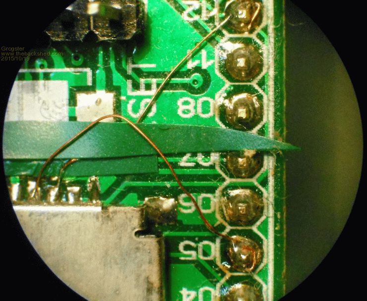
Hi G, I have multiple setups (prototypes) here that use various length wires to the SD card. My latest unit however seemed to cause issues with FILES fspec$ but it has been confirmed that there is a bug. Initially I thought it was wire length but all is ok. I have had up to about 12cm from EXPLORE64 edge pin to back of SD socket. So add on the track length too and that is easily 15cm from PIC to SD socket. I have used both micro and standard size cards - no issues with either. DO remember there are different pin-outs for the two different socket types 
The only issues I have had are with the WP/CD pins on the SD socket. Sometimes the clearance between them and the metal body is so close that the pin gets 'earthed out' and allows a 'locked' card to be written to (or detected incorrectly). BUT this is when I hand solder a hair wire direct to the socket (so is human error) but with a man of your PCB skills this won't be an issue! 
WW |
||||
Grogster Admin Group Joined: 31/12/2012 Location: New ZealandPosts: 9877 |
OH yes..... The MM+ Explore 64 I designed for Geoff had a mistake with the uSD card, cos I thought they(SD and uSD) would be the same feckin' pinout- curses!!! 

Luckily, this was the 1A board, and being an alpha, you are allowed mistakes.    Smoke makes things work. When the smoke gets out, it stops! |
||||
MicroBlocks Guru Joined: 12/05/2012 Location: ThailandPosts: 2209 |
Yeah standards are so great it is time for a new one. :) I think we all go through the same mistakes as this is one i have done too. Cursing why it did not work when all the signals are correct at the mcu pins side.  Microblocks. Build with logic. |
||||
| The Back Shed's forum code is written, and hosted, in Australia. | © JAQ Software 2026 |