
|
|
Forum Index : Microcontroller and PC projects : uM2(+): wire graphics using quaternions
| Page 1 of 2 |
|||||
| Author | Message | ||||
| matherp Guru Joined: 11/12/2012 Location: United KingdomPosts: 11499 |
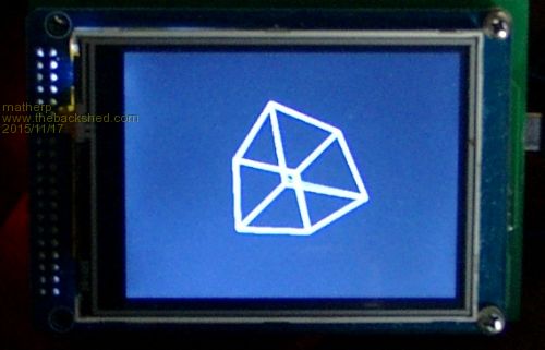
Please excuse the picture, my good camera isn't available. This is a demo program (all in Basic) of some interesting maths that underpins all sorts of technologies like attitude/heading systems and 3D graphics. Quaternions are a mathematical technique that allows the rotation in any direction of any shape. The maths behind it are way beyond me and extend the concept of complex numbers such that: i*i == j*j == k*k == i*j*k == -1 I find that equation completely bemusing 
However, quaternions are pretty easy to use in the real world. There are some gotchas: quaternions are not commutative e.g q1 * q2 does not give the same result as q2 * q1. But overall the calculations are pretty simple. The attached code draws a wireframe cube and then rotates it continuously in the directions specified by the rotation quaternion. The cube is specified as a set of coordinates around a point 0,0,0 in the array "cube". Then the array cubelines% is used to store the coordinate pairs that make up the lines that draw the cube. The array "cubelocation" defines the actual position of the cube in space. The x and y axes are as per the display and the z axis comes out of the display towards the viewer. The code uses a projection method of perspective to visualise the cube in 2 dimensions and "viewplane" defines the location of the projection plane in the z axis. All quaternion arithmetic is carried out with the quaternion normalised. The subroutine "create_normalised_quaternion" takes a rotation vector and an angle and converts it into a quaternion. Then to rotate a point we just multiply the rotation quaternion by the normalised coordinates of the point and then multiply the answer by the inverse of the quaternion. Note how in normal math this would leave the point unchanged but because of the non-commutative nature of the quaternion somehow the sequence does what we want (look at Jorge Rodriguez excellent videos on Youtube if you want to know more). Note that no trigonometry is needed other than in the initialisation of the rotation quaternion and that only uses the sine and cosine of a single angle. The attached code includes all the routines necessary to rotate objects in 3D and then project them onto a 2D screen. My interest is in using the math to understand what is happening inside a Attitude and heading reference system (AHRS), but the example code below is quite fun. The code should run on any type of Micromite with a connected TFT display. The picture is of a 320x240 SSD1289 display driven by a 44-pin uM2. Play with this line: create_normalised_quaternion(2,1,0,0,q1()) to change the way the cube rotates. The parameters are: number of degrees to rotate about the rotation vector x-coordinate of the end of the rotation vector y-coordinate of the end of the rotation vector z-coordinate of the end of the rotation vector array to receive the quaternion Enjoy 
option explicit option default FLOAT cpu 48 ' 3D wire frame graphics demo using quarternions to rotate the coordinates cls dim q1(4),v(4),vout(4),M_PI=3.14159265359,i%,x1,y1,z1,x2,y2,z2 ' define the coordinates of a cube with the z-axis towards the viewer dim cube(3,7)=(-100,-100,100,0, -100,100,100,0, 100,-100,100,0, 100,100,100,0, -100,-100,-100,0, -100,100,-100,0, 100,-100,-100,0, 100,100,-100,0 ) 'coordinates of the cube ' define the coordinate pairs that make up the edges of the cube DIM cubelocation(2)=(mm.hres/2,MM.VRES/2,-500) 'actual location of the centre of the cube in space ' define the coordinate pairs that make up the edges of the cube dim cubelines%(1,11)=(0,1, 0,2, 1,3, 2,3, 4,5, 4,6, 5,7, 6,7, 0,4, 1,5, 2,6, 3,7) 'define the projection plane DIM viewplane = -200 dim lines%(3,11),oldlines%(3,11) 'storage for the coordinates for lines drawn for i%=0 to 7 'convert coordinates to normalised form x1=cube(0,i%): y1=cube(1,i%): z1=cube(2,i%) create_vector(x1,y1,z1,v()) cube(0,i%)=v(2): cube(1,i%)=v(3): cube(2,i%)=v(4): cube(3,i%)=v(0) next i% 'create a quarternion to rotate 2 degrees about x axis 'play with the x,y,z vector which is the sxis of rotation create_normalised_quaternion(2,1,0,0,q1()) do for i%=0 to 11 'project the coordinates onto the viewplane z1=cube(2,cubelines%(0,i%))*cube(3,cubelines%(0,i%))+cubelocation(2) x1=(cube(0,cubelines%(0,i%))*cube(3,cubelines%(0,i%))*viewplane/z1 +cubelocation(0)) y1=(cube(1,cubelines%(0,i%))*cube(3,cubelines%(0,i%))*viewplane/z1 +cubelocation(1)) z2=cube(2,cubelines%(1,i%))*cube(3,cubelines%(1,i%))+cubelocation(2) x2=(cube(0,cubelines%(1,i%))*cube(3,cubelines%(1,i%))*viewplane/z2 +cubelocation(0)) y2=(cube(1,cubelines%(1,i%))*cube(3,cubelines%(1,i%))*viewplane/z2 +cubelocation(1)) lines%(0,i%)=x1 :lines%(1,i%)=y1 :lines%(2,i%)=x2 :lines%(3,i%)=y2 next i% for i%=0 to 7 'rotate coordinates v(2)=cube(0,i%): v(3)=cube(1,i%): v(4)=cube(2,i%): v(0)=cube(3,i%): v(1)=0 rotate_vector(vout(),v(),q1()) cube(0,i%)=vout(2): cube(1,i%)=vout(3): cube(2,i%)=vout(4): cube(3,i%)=vout(0) next i% for i%=0 to 11 'delete the old lines line oldlines%(0,i%),oldlines%(1,i%),oldlines%(2,i%),oldlines%(3,i%),1,rgb(black) next i% for i%=0 to 11 'draw the new lines line lines%(0,i%),lines%(1,i%),lines%(2,i%),lines%(3,i%),1,rgb(white) oldlines%(0,i%)=lines%(0,i%):oldlines%(1,i%)=lines%(1,i%):oldlines%(2,i%)=lines%(2,i%):oldlines%(3,i%)=lines%(3,i%) next i% loop end ' sub create_normalised_quaternion(theta,x,y,z,q()) local radians = theta/180.0*M_PI local sineterm= sin(radians!/2) q(1)=cos(radians/2) q(2)=x* sineterm q(3)=y* sineterm q(4)=z* sineterm q(0)=sqr(q!(1)*q(1) + q(2)*q(2) + q(3)*q(3) + q(4)*q(4)) 'calculate the magnitude q(1)=q(1)/q(0) 'create a normalised quaternion q(2)=q(2)/q(0) q(3)=q(3)/q(0) q(4)=q(4)/q(0) q(0)=1 end sub ' sub invert_quaternion(n(),q()) n(0)=q(0) n(1)=q(1) n(2)=-q(2) n(3)=-q(3) n(4)=-q(4) end sub ' sub multiply_quaternion(n(),q1(),q2()) local a1=q1(1),a2=q2(1),b1=q1(2),b2=q2(2),c1=q1(3),c2=q2(3),d1=q1(4),d2=q2(4) n(1)=a1*a2-b1*b2-c1*c2-d1*d2 n(2)=a1*b2+b1*a2+c1*d2-d1*c2 n(3)=a1*c2-b1*d2+c1*a2+d1*b2 n(4)=a1*d2+b1*c2-c1*b2+d1*a2 n(0)=q1(0)*q2(0) end sub ' sub create_vector(x,y,z,v()) v(0)=sqr(x*x + y*y + z*z) v(1)=0 v(2)=x/v(0) v(3)=y/v(0) v(4)=z/v(0) end sub sub rotate_vector(vnew(),v(),q()) local n(4),iq(4) multiply_quaternion(n(),q(),v()) invert_quaternion(iq(),q()) multiply_quaternion(vnew(),n(),iq()) end sub |
||||
| twofingers Guru Joined: 02/06/2014 Location: GermanyPosts: 1752 |
Hi Peter, you scare me. Do you never sleep?
It looks very nice on my MX170. I would never expect that this could be done in pure basic. It gives me a ELITE feeling. 
Thanks! 
Michael EDIT I like this: create_normalised_quaternion(4,1,3,3,q1()) causality ≠ correlation ≠ coincidence |
||||
| WhiteWizzard Guru Joined: 05/04/2013 Location: United KingdomPosts: 2991 |
Got half way through your post and now my head is spininng too as well as the cube!!
Is it recommended on an SPI display (ILI9341) or are these way too slow? I am not near a MM at the moment but have always wanted to 'animate' a cube in the corner of a TFT (spinning logo effect). WW |
||||
| matherp Guru Joined: 11/12/2012 Location: United KingdomPosts: 11499 |
Should be fine |
||||
| twofingers Guru Joined: 02/06/2014 Location: GermanyPosts: 1752 |
I can confirm! causality ≠ correlation ≠ coincidence |
||||
| WhiteWizzard Guru Joined: 05/04/2013 Location: United KingdomPosts: 2991 |
Thanks for confirming gents. Now I really need to get in front of a MM to give this a try asap; interested in the 'smoothness'! @matherp: So what is tonights exciting new code project you are working on? You never cease to amaze us . . . |
||||
| paceman Guru Joined: 07/10/2011 Location: AustraliaPosts: 1329 |
That's really interesting Peter, I'd never heard of quaternion arithmetic. You can certainly see how it must speed things up by not having to constantly call trig functions though. I tried both your example and Michael's (his is 'groovier', sorry ), and his 'tumbling' one also seems to give the illusion of drawing a bit faster than your rotation on horiz axis one. That wouldn't be the actual case I suppose but it's interesting.
It's certainly a bit flickery on my 170/ili9341 setup but quite usable I'd say. No doubt a CFunction would trounce the flicker. 
Greg |
||||
| WhiteWizzard Guru Joined: 05/04/2013 Location: United KingdomPosts: 2991 |
@matherp Something you have 'uncovered' on a product I am soak testing. With a 100pinner and an ILI9341, your code runs ok for about one minute and then the TFT resets (backlight on, display as if not 'configured' by MM+). However, the MM+ is still running ok (as are all other hardware modules). Any other software I use that incorporates the TFT runs fine without resetting the TFT. Any ideas as to why this code could reset the TFT? I have not yet put an analyser on the RESET line to see if it is somehow getting one - will do that later. Is anyone else seeing their TFT go 'blank'. By the way, I am using a blue background, and have amended the line of code LINE OLDLINEs%... from RGB(BLACK) to RGB(BLUE); and CPU 48 to CPU 100 EDIT: And using: create_normalised_quaternion(4,1,3,3,q1()) I will go back to original just to make sure it isn't these changes causing the issue. WW |
||||
| WhiteWizzard Guru Joined: 05/04/2013 Location: United KingdomPosts: 2991 |
FYI: Reverting back to: create_normalised_quaternion(2,1,0,0,q1()) seems to have fixed it??
I will continue testing . . . . |
||||
| matherp Guru Joined: 11/12/2012 Location: United KingdomPosts: 11499 |
WW All the various symptoms you are experiencing in the various problems you are having point to me to instability in the SPI bus and/or control bus to the display. My code does nothing odd except that it draws a lot of diagonal lines. These are very heavy as for each individual pixel the processor will be sending about 14 bytes and repeatedly toggling CD and CS. At any time if the graphics processor interprets CD incorrectly or a command byte miss-framed then data could be misinterpreted as a command and cause problems. All my testing is now on one of my backpack PCBs (44-pin or 64-pin) with no signals going "off-board" and I don't see any of the problems you are getting. The changes you have made can't possibly be a problem except in that there is slightly different data on the SPI bus which may be more sensitive to corruption. Try: create_normalised_quaternion(2,1,1,1,q1()) This rotates about two opposing vertices. Note the first parameter is just the angle of rotation for each iteration changing from 2 to 4 just makes the cube rotate faster but less smoothly |
||||
| WhiteWizzard Guru Joined: 05/04/2013 Location: United KingdomPosts: 2991 |
I agree Peter, now that I've experienced a number of 'issues', the common factor is definitely the SPI2 bus (SD card, and TFT issues). When I tried 2,1,1,1 there was about 9 seconds before a 'reset' was observed (for the TFT only). I am getting a PCB designed this week, and hoping to make it next week. Truly hope that a PCB will resolve all the issues
Thanks for your patience with this. At least it is highlighting a 'gotcha' that other people may get caught out by! Out of interest, which would stress the SPI more? I would have thought drawing at 'angle of rotation' = 1 would be passing more data in a given time (but this is not reseting the TFT); whereas rotating at a larger angle would pass less data (even though it appears to obviously 'spin' faster'). So in summary, I have had issues with: LOAD IMAGE drawing a staggered/pixelated image (but type of SD card sometimes results in the .bmp being drawn ok) GUI TEST LCDPANEL stopping the circles after a few seconds but only after a power up (however, if I do any SD function before the TEST the circles continue ok) and now the spinning cube (but depends upon 'spin angle') For information to others, my cables between the MM PCB and the TFT module/PCB are no more than 10cm in length. Initially I used ribbon cable, but then thought crosstalk could be causing the issues, so then put a ground cable between each signal line (bu no difference). Then split the ribbon so effectively just jumper cables - still had issues. WW |
||||
| paceman Guru Joined: 07/10/2011 Location: AustraliaPosts: 1329 |
Mine's set up on two smallish, very ordinary, rather 'used' breadboards with 9341 display on one board and the 170 and 1A supply on the other. There are 14x20cm DuPont jumpers in all and all three sets of quaternion parameters mentioned run without a problem - for the several minutes I've run each of them anyway. Given your hassles Phil I guess I'd have to say I'm lucky. Greg |
||||
| WhiteWizzard Guru Joined: 05/04/2013 Location: United KingdomPosts: 2991 |
It could be the 'cheap' TFT. I ordered others from UK eBay suppliers but they do the same thing unfortunately. Will try ordering an ILI9341 direct from a TFT manufacturer and wait until 2017 for it to arrive . . . . Thanks for letting me know that yours worked  Obviously knowing that doesn't make me feel any better at all!!! Obviously knowing that doesn't make me feel any better at all!!!
WW |
||||
kiiid Guru Joined: 11/05/2013 Location: United KingdomPosts: 671 |
Phil, I've got a few unwanted 2.8" ILI9341 displays (the red boards) laying around. Wouldn't mind sending you one or two if you need it urgently. These are proven perfectly working ones. http://rittle.org -------------- |
||||
| WhiteWizzard Guru Joined: 05/04/2013 Location: United KingdomPosts: 2991 |
Hi Kon, I am definitely interested in at least one of them to try out if possible. PM (or email) me to let me know how much including shipping (I can PayPal you straight away). Will give you postal details by return PM/email. Thanks . . . . . WW |
||||
| twofingers Guru Joined: 02/06/2014 Location: GermanyPosts: 1752 |
I use a BP170 and a chinese 2.4" ILI9341 display without any problems. I can't imagine that Peters code can overstress this displays. Maybe a different pin layout could help to catch the issue. My pin layout (BP170): OPTION LCDPANEL ILI9341, L, 4, 5, 6
OPTION TOUCH 7, 2 "> 
I used Peters code to make a MM Screensaver (assuming it's okay for Peter to post it here). This is a DEMO to show the versatility.
Michael EDIT: BTW. the framerate is ~8 FPS on a MX170/28 @48MHz. causality ≠ correlation ≠ coincidence |
||||
TassyJim Guru Joined: 07/08/2011 Location: AustraliaPosts: 6538 |
@Phil Peters original code has been running happily on my 100pin 470 / 2.4in TFT for about 4 hours now without problems. Board is Snadpic with cheap Ebay display. Jim VK7JH MMedit |
||||
| isochronic Guru Joined: 21/01/2012 Location: AustraliaPosts: 689 |
I clicked on the image above ( the "click me" graphic ) ..I expected a small video like a youtube clip. But it sent a zip file instead, I would guess with the quaternion basic source ( don't know as I deleted it ). Was that the intent ? (I'm not after quaternion code, just thought it would be a nifty video) |
||||
| WhiteWizzard Guru Joined: 05/04/2013 Location: United KingdomPosts: 2991 |
WHAT IS GOING ON? 
If I type FILES before running the spinning Cube program, the cube keeps spinning and the program doesn't crash. BUT, if I don't perform an SD card function (i.e. FILES), then the program crashes out after just a few seconds. So what causes this (and GUI TEST LCDPANEL) to only work properly AFTER I have performed an SD card function? I do now have other TFTs to try out (thanks to kiid ).
But why is it that this one is behaving like this? I am beginning to doubt it is a local issue even though I am the only person witnessing it at the moment! Yes I do believe it is related to the SPI2 bus (with combined Touch, TFT, and SD card); but all these things do work. If it were 'stray' capacitance, then why does everything work AFTER I perform an SD function (the demonstrable and consistent way that works 100% of the time). Yet, when I don't perform an SD function, the SPI bus gets 'corrupted' somehow. Probably one for Geoff or Peter: Is there anything that you think could be on the TFT that is faulty that could be causing this? I have cabled, and re-cabled many times so I don't accept it is my cabling. Also, power supply changed and is good and stable (and remember everything works fine IF I perform an SD card function first indicating it is not a hardware issue IMHO). I will try other TFTs when next at home (now on the road until late Sunday), and also have a PCB soon to eliminate any cable issues. Just asking for any 'glimmer' of a clue . . . .
|
||||
| matherp Guru Joined: 11/12/2012 Location: United KingdomPosts: 11499 |
WW I've just checked all the SPI registers under all the scenarios you have identified and they are always correct. I've also put the SPI clock on the scope and it is exactly as you would expect. I'm running 64-pin with ILI9163 and SDcard and touch. It works perfectly. I really don't believe there is any firmware issue. Have you ever demonstrated the problem when using the on-display SDcard slot? If not can I suggest you completely disconnect your separate SDcard slot and use the one on the display as a test. Also, is the problem sensitive to CPU speed? To me everything suggests the problem is something to do with the SD card wiring and not the display. A full circuit diagram would be helpful. The speed the SPI bus runs at 100MHz is 12.5MHz. Other platforms are running the ILI9341 at 20MHz so we are well within the capabilities of the controller. |
||||
| Page 1 of 2 |
|||||
| The Back Shed's forum code is written, and hosted, in Australia. | © JAQ Software 2026 |
