
|
|
Forum Index : Microcontroller and PC projects : HC-12 Wireless Serial Module
| Author | Message | ||||
| HankR Senior Member Joined: 02/01/2015 Location: United StatesPosts: 209 |
Grogs, That's the same video I linked to a few posts back. I did miss the part about devices he got to work and which ones he didn't. The reason being is that I skipped the first few minutes to save a little time and I figured his overall findings would be near the conclusion of the video. So it's good that you gave it a better look than I did this time around. I find this all a little odd, and I hope we can figure out what the heck is going on eventually. I wonder if just the -11 has this odd behavior or whether the -12 will show it at some point. Apparently Rob didn't run into it at all. I think a year ago the -12 was somewhat more expensive. Now it's just a few cents more, so maybe I'll get a pair of those and stay clear of the -11s until this is sorted out. Hank |
||||
Grogster Admin Group Joined: 31/12/2012 Location: New ZealandPosts: 9059 |
I do have four of these HC-12's coming, so I will see what happens when they get here. I am hopeful that the 12's won't have the 11's PIC32 communication problem. Smoke makes things work. When the smoke gets out, it stops! |
||||
| HankR Senior Member Joined: 02/01/2015 Location: United StatesPosts: 209 |
Oh boy! Grogs is using an expression of his own, true-type-logic, and I think it's derived in part from language that the PICAXE people came up with. A wee bit of confusion possible right there because of the standard use of the TTL abbreviation, Transistor-Transistor-Logic. Okay, stay with me folks. It gets worse. PICAXE uses the terms "true" and "inverted" for their direct-from-the-uC serial output (no intervening MAX232, no inverting buffer ICs or discrete transistors). When you employ PICAXE "true mode" serial, your polarity is in fact INVERTED compared to a by-the-rules, official RS-232 signal. When you employ PICAXE "inverted" serial, your polarity is in fact NOT INVERTED compared to the official RS-232 standard. So a PICAXE set to "True serial output (as defined by the PICAXE organization), serially connected to a uMite or any other uC, will work because both devices are using INVERTED RS-232 signals. ------------------------------------------ Notes: Idle mode in official RS-232 is a negative voltage or low logic level. Taken right from PICAXE.com for serin command: Txxx give a true output (idle high). Nxxx give an inverted output (idle low). ------------------------------------------ I've tried to double check everything I've done here, but mistakes are possible. Hank |
||||
CircuitGizmos Guru Joined: 08/09/2011 Location: United StatesPosts: 1421 |
On the chip signal level, I agree with this phrasing. Right out of the microcontroller, idle would be 3.3V/5V and the start bit would be 0V. That is the 'normal' level into the RS232 driver chip. Every computer in the 1980s+ used a UART chip + an RS232 driver. It was 5V idle and 0V start bit out of the UART. The RS232 chip then changed the levels to -12V idle and +12V start bit to drive the line. So another way to look at it is that the 'true' level is appropriate for use of an RS232 driver, the way that you need to do RS232 for reliability. Calling any signal that comes out of a microprocessor "RS232" is incorrect. RS232 defines the signal voltage after the appropriate driver for the physical line. The UART output is at logic level only, not line voltage levels. The same UART output at logic levels can also drive an RS485 driver/interface. The logic level signals are identical, the line driver is different. If you skip the drivers (and connecting cables) and connect the output (UART output) of microcontroller A to the input of microcontroller B, the levels are all 'true'. There are no RS232 voltage levels involved. -------------------- The guys at picaxe realized if you invert the normal UART levels (idle high, start bit low) to be idle low, then many, but not all, RS232 transceivers would accept the not-quite-right voltage levels. In other words: Normal idle is 5V which becomes -12V after RS232 level conversion. Normal start bit is 0V which becomes +12V after RS232 level conversion. The picaxe 'inverted' output for idle = 0V which when connected to many RS232 RECEIVERS is as acceptable as an idle state as -12V would be. The picaxe 'inverted' output for start = 5V which when connected to many RS232 RECEIVERS is as acceptable as an start state as 12V would be. The 'inverted' feature takes advantage of the wide acceptance range of some RS232 receivers in order to be cheap and eliminate an RS232 transceiver. Micromites and Maximites! - Beginning Maximite |
||||
| Grogster Admin Group Joined: 31/12/2012 Location: New ZealandPosts: 9059 |
I stand corrected. Yes, that was my definition of TTL - True-type-logic, but you are absolutely correct - the appropriate definition is actually Transistor-transistor-logic, as you point out. See This link on TTL for further correct definitions.  Smoke makes things work. When the smoke gets out, it stops! |
||||
| Grogster Admin Group Joined: 31/12/2012 Location: New ZealandPosts: 9059 |
I have finally had a chance to play with these modules, and my initial thought is: "Impressive." They are dead easy to get working, and the range with default settings and the little spring aerials is also quite good even through walls. Default output power is 100mW though, so I would expect it to have reasonable range with that power, and excellent range line-of-sight with that power. I much like the little micro antenna socket so that you could elect to use an external SMA antenna if you wanted, which should make the performance even better. Tomorrow, I will do a proper range test walk-around outside, but I already have plans for these little modules, cos the price-vs-power is certainly a sweet-spot. I will also hook one up to the spectrum analyser, and see what the harmonics are like. The output might be dirty, which would explain the price to some extent, but looking at the module's output stage on the microscope, it would appear they are using some sort of basic RF filtering there. At first glance, and without a schematic to go on... 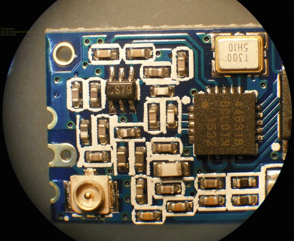
Smoke makes things work. When the smoke gets out, it stops! |
||||
| HankR Senior Member Joined: 02/01/2015 Location: United StatesPosts: 209 |
What kind of socket is that tiny thing? I think it's the same as on my HC-11. |
||||
| srnet Senior Member Joined: 08/08/2014 Location: United KingdomPosts: 164 |
Its a UFL. You can get UFL to SMA socket leads for around �1 delivered on eBay. $50SAT is Silent but probably still working. For information on LoRa visit http://www.loratracker.uk/ |
||||
| Grogster Admin Group Joined: 31/12/2012 Location: New ZealandPosts: 9059 |
RF output @ 100mW directly into analyser via UFL socket on default frequency: 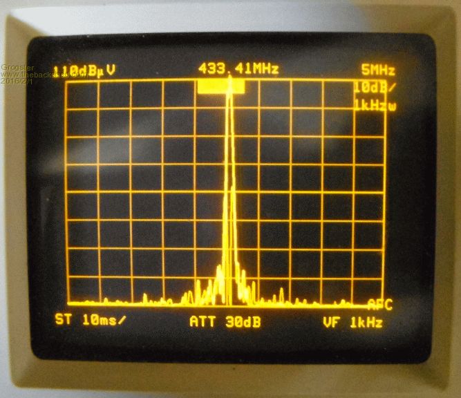
Spectral purity, showing 2nd harmonic - 3rd harmonic is immeasurable: 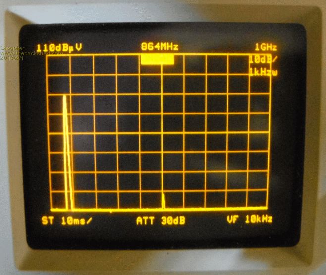
Considering the price of these units vs the output power, I am actually very surprised at how clean they appear to be in some basic analyser tests. I am indeed impressed. 2nd harmonic @ 866.8MHz was better then 70dB down on the carrier, and the 3rd harmonic was totally invisible, as you are into floor noise by then - this is very good performance in my humble opinion, and I would happily recommend these modules to a friend.
(EDIT: That should be 1st Harmonic was 70dB down on the carrier, and 2nd and 3rd immeasurable. Excellent, IMHO.) As mentioned before, this is not exactly a lab-level test, but it does result in some useful information as to what they actually emit onto the spectrum. ...hard to get over the price of the things for the output power - I was SURE they would have a dirty output at that price(cos something has to give, and it's usually the output filtering), but... Smoke makes things work. When the smoke gets out, it stops! |
||||
| HankR Senior Member Joined: 02/01/2015 Location: United StatesPosts: 209 |
G, You had it right the first time: the second harmonic is 868.8 MHz. The first harmonic is rarely used in conversation, but it refers to the fundamental. H |
||||
| HankR Senior Member Joined: 02/01/2015 Location: United StatesPosts: 209 |
Thanks for that info and thanks for uploading the pics of the module and the spec analyzer screen. I'm going to ask you a question by PM about that measurement. After seeing it was a U.FL and googling that, I found that it's also known as an IPEX and about 4 other names. The Silicon Labs tech. literature calls it an IPEX. It's actually a patented design first assigned to Hirose, and the US patent expired early because of non-payment of routine maintenance fees. I would like to find a pigtail to go direct from U.FL to BNC. |
||||
| Grogster Admin Group Joined: 31/12/2012 Location: New ZealandPosts: 9059 |
Like this? ...or this one? EDIT: Oh, and srnet said that bit you have quoted as coming from me. Smoke makes things work. When the smoke gets out, it stops! |
||||
| HankR Senior Member Joined: 02/01/2015 Location: United StatesPosts: 209 |
Thanks, srnet. |
||||
lew247 Guru Joined: 23/12/2015 Location: United KingdomPosts: 1676 |
Can you confirm that you have to have the set pin low to get the config utility to work please? |
||||
| Grogster Admin Group Joined: 31/12/2012 Location: New ZealandPosts: 9059 |
Confirmed. SET must be pulled LOW for the module to enable setting mode. Smoke makes things work. When the smoke gets out, it stops! |
||||
| CircuitGizmos Guru Joined: 08/09/2011 Location: United StatesPosts: 1421 |
Thanks to the influence of Grogster  I went out and bought a couple modules to play with. Then I looked again and realized that they came in pairs. These are really inexpensive. I went out and bought a couple modules to play with. Then I looked again and realized that they came in pairs. These are really inexpensive.Micromites and Maximites! - Beginning Maximite |
||||
| HankR Senior Member Joined: 02/01/2015 Location: United StatesPosts: 209 |
I've spoken to grogster, and there is just a little mistake here in the magnitude of the 2nd harmonic. For the record, from the screenshot, 866 MHz is down by a little more than 50 dB. |
||||
| JohnL Senior Member Joined: 10/01/2014 Location: SeychellesPosts: 128 |
Can owners/users of HC-12 confirm if it actually DOES or DOES NOT support AT+A, set ID address? I know AT+A is not listed in the documentation, but would like to know if anyone has actually tried it in practice. Less powerful HC-11 10dba is documented to support AT+A, set ID address. Regards John |
||||
| Grogster Admin Group Joined: 31/12/2012 Location: New ZealandPosts: 9059 |
I can try that for you if you like with one of my modules. Can you give me a syntax example, as a quick search of Google resulted in nothing useful for "AT+A", surprisingly.... Smoke makes things work. When the smoke gets out, it stops! |
||||
| JohnL Senior Member Joined: 10/01/2014 Location: SeychellesPosts: 128 |
Thanks Grogs, As per HC-11 manual example. To set module address to be 12. Send "AT+A012" to module. (A012 = Azero12, number 0 not letter O). Module should return "OK-A012" Not sure if you need to actually type "" around the AT commands? There is AT+Ry to check module parameters. if y = B , will return baud rate setting. C, will return RF channel. I assume A should return module ID address, if it works. AT+RX should return ALL preset parameters. Regards John |
||||
