
|
|
Forum Index : Microcontroller and PC projects : SD Card Connection
| Page 1 of 2 |
|||||
| Author | Message | ||||
| circuit Senior Member Joined: 10/01/2016 Location: United KingdomPosts: 299 |
I have just started using MMBasic on the UBW32 board - a fantastic system. I have uploaded the MMBasic and the thing is up and running. Following the advice in Geoff's "Colour MMBasic on the UBW32 Board - Implementation Manual" I purchased the recommended Sparkfun SD Card breakout board (https://www.sparkfun.com/products/12941). The board has more connectors than I expected and I am having difficulty sorting out the connection to the UBW32 board. The pin-outs are labelled; D2; D3; CMD; CD; CLK; VCC; GND; D0; D1; WP. I assume that CLK goes to F13; WP to D6; CD to A1 but then I am stuck... The UBW connects are labelled "data to card" and "data from card" but I have the D0;D1;D2 and D3 remaining. Can anyone help me with the appropriate connections please? |
||||
| WhiteWizzard Guru Joined: 05/04/2013 Location: United KingdomPosts: 2962 |
@circuit The Sparkfun labeling is for when the SD card is used in 'SD' mode. For the MicroMite, it is used in SPI mode. Google will help translate between the two. To save you time; the following should work: D2 = leave unconnected D3 = leave unconnected CMD = Data from MicroMite to SD Card (SPI MOSI) CD = MicroMite CS (card select) CLK = MicroMite SPI SClk VCC = 3v3 GND = (take a guess!) D0 = Data from SD Card to MicroMite (SPI MISO) D1 = leave unconnected WP = Write Protect detect signal to any configurable MicroMite pin (set in OPTION SDCARD) One word of warning; avoid the 'older' 2G SD cards as many have proven too unreliable. 4G+ are cheap enough now and will save you a great deal of head-scratching!! Best of luck . . . WW |
||||
| circuit Senior Member Joined: 10/01/2016 Location: United KingdomPosts: 299 |
Most helpful; thank you very much indeed. |
||||
| circuit Senior Member Joined: 10/01/2016 Location: United KingdomPosts: 299 |
This afternoon I tried to apply the advice given; I regret that I am, once again, a little confused. I am using a UBW32 and this uses Colour MMBasic; not Micromite Basic. I can find no reference in Colour MMBasic 4.5 to OPTION SDCARD (I am familiar with this option when I use Micromite+ but does it apply to the UBW32 MMBasic?). The terminology used in the Micromite Plus manual seems to confuse me also; it defines the "CD-pin" as "card detect" whereas in the advice given by WhiteWizzard the connection advised is to connect CD to Card Select... Right now, I think this to be correct, but I would ask that those with knowledge check it out for me before I commit the wiring. 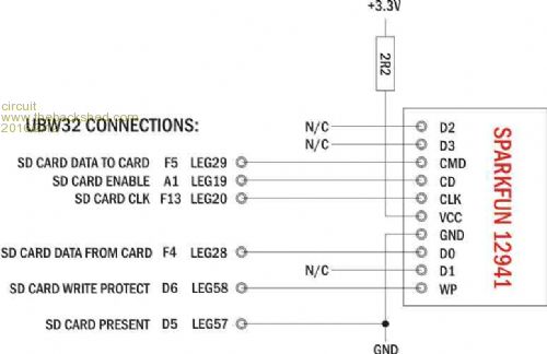
|
||||
| circuit Senior Member Joined: 10/01/2016 Location: United KingdomPosts: 299 |
Something further to add; I see some references to the D3 pin on the Sparkfun board being the CS or Chip Select input for the SPI interface. I am confused whether the A1 (leg19) SD Card Enable is an output or input; I am thinking it is the output to the SD card CS? |
||||
| circuit Senior Member Joined: 10/01/2016 Location: United KingdomPosts: 299 |
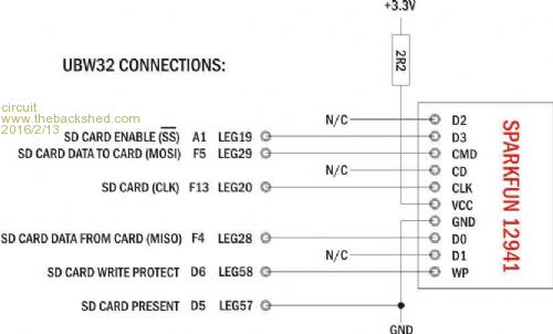
I have been searching around for information and now I have come to the conclusion that the CARD ENABLE line is the SPI chip select line and therefore should be connected to D3 on the Sparkfun board. Hence the revised schematic above. Any help out there? I don't want to try it out in case I connect two outputs to each other or suchlike and blow an SD card. |
||||
| akashh Senior Member Joined: 19/01/2014 Location: IndiaPosts: 115 |
On the topic of sd cards, I spent about three weeks debugging a what I was sure was a software issue that was causing random crashes and memory corruption. Finally I traced it to random noise glitches in the sd card data. I was running the sd at 40mhz and by going down to 20 I increased the reliability tremendously. I had 100k pull ups on all the sd card lines. The cause for the noise seems to be a 433 MHz wireless transceiver mounted nearby. The point I wanted to share is that by reducing the pull up values to 5.1k I was able to still operate at 40mhz without issues but chose to lower the rate as an extra precaution. I am not sure if 5.1k is a good value to use on an sd card line, could anyone suggest an alternative or confirm that it is fine? |
||||
| robert.rozee Guru Joined: 31/12/2012 Location: New ZealandPosts: 2498 |
assuming open-collector outputs, it is amazing things worked at all with 100k pullups on data and clock lines. something between 3k3 and 10k would be far more normal. cheers, rob :-) |
||||
| circuit Senior Member Joined: 10/01/2016 Location: United KingdomPosts: 299 |
Guys, you are introducing a new aspect; pull-ups? There is no mention in the UBW32 MMBasic Manual (http://geoffg.net/Downloads/Maximite/Colour%20Maximite%20on%20the%20UBW32.pdf)of pull-ups on any of the lines. They do not appear in Geoff's schematic on page 4 of the manual. Where and why are these needed? |
||||
| matherp Guru Joined: 11/12/2012 Location: United KingdomPosts: 11107 |
Suggest you start from first principles look at Geoff's circuit for the Colour Maximite Buzz out the wires on the SD card/UBW32 as shown in the diagram and connect in the same way |
||||
| robert.rozee Guru Joined: 31/12/2012 Location: New ZealandPosts: 2498 |
i did include the proviso: "assuming open-collector outputs...". i have just now checked the colour maximite schematic, and 'circuit' is right, there are no pullups shown. this implies that the pins are driven in both high and low states, raising the interesting question as to why 'akashh' found a need to include them. i know not the answer! could someone with access to the source code chip in? geoff? cheers, rob :-) |
||||
| circuit Senior Member Joined: 10/01/2016 Location: United KingdomPosts: 299 |
Oh, dear! We seem to be going around in a full circle. The quoted schematic is, of course, amongst those that I am working from. I have purchased the SD Card connector that Geoff references in his UBW32 manual and the SD Card wiring is the same as the Maximite schematic, but the pin-outs on the recommended card do not correspond with the schematic - that is my problem. All that I want is to know precisely which UBW32 pins I connect to each of the terminals on the SD Card. I am presuming that SparkFun may perhaps have changed the card type since Geoff drew the schematic. For clarity, this is the SD Card Connector; 
My latest thoughts are that the connections should be: 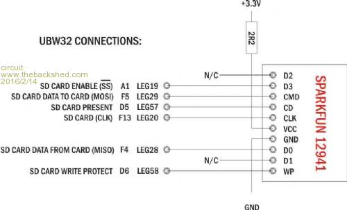
Can ANYBODY confirm or correct this, please? I note that Geoff's schematic is three years old and therefore are there any recommended modifications from experience or otherwise with regard to the installation of pull-ups as mentioned by Robert Rozee? |
||||
Grogster Admin Group Joined: 31/12/2012 Location: New ZealandPosts: 9918 |
Your SD wiring needs to follow this graphic: 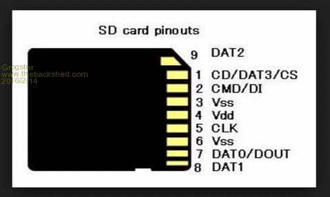
SD cards(all types) can be used in one of two modes: SPI(what we want), or 4-bit mode. Pin1 of the SD card needs to go to pin38 of the CMM Pin2 of the SD card needs to go to pin50 of the CMM Pin3 of the SD card needs to go to ground. Pin4 of the SD card needs to go to 3v3 via the 2R2 resistor. Pin5 of the SD card needs to go to pin39 of the CMM. Pin6 of the SD card needs to go to ground. Pin7 of the SD card needs to go to pin49 of the CMM. Pin8 of the SD card needs to be unconnected. Pin9 of the SD card needs to be unconnected. Card Detect(CD) on the SD card needs to go to pin82 of the CMM. Write Protect(WP) on the SD card needs to got to pin83 of the CMM. Those last two pins are optional, but if you plan to use them, you must connect them. That should get you up and running. It is important to note that the CMM does not allow you to pick and choose the PIC32 pins to use - they are set in the firmware, so you MUST use the pins in the list above, which I note that in your diagrams, you are not... EDIT: I note you are referring to 'Legs' in your diagrams, which may well end up being the PIC32 pin numbers as above - I will have to check. Assuming it IS correct, then it should be working. Smoke makes things work. When the smoke gets out, it stops! |
||||
| circuit Senior Member Joined: 10/01/2016 Location: United KingdomPosts: 299 |
Grogster, thank you. Yes, my reference to "Leg" is to the arrangement of the connections on the periphery of the UBW32 board, not the PIC - and I have checked as far as I can and these do seem to correspond with the "CMM Pin numbers" that you quote. My problem lay, I think, in that there was no clear and obvious correspondence between the SD Card pin numbers and the arrangement of connections on the recommended SparkFun card. Now that I have (with everyone's kind help) brought myself up to speed with SD Card technology - which I have to admit complete ignorance of initially - I think that my final proposed diagram is, indeed, the correct interpretation. I will give it a go in hard wiring tomorrow. |
||||
| Grogster Admin Group Joined: 31/12/2012 Location: New ZealandPosts: 9918 |
I found an old board design that used the UBW32 module, and I had my SD card wired as: SD card pin1 to UBW32 leg A0 SD card pin2 to UBW32 leg F5 SD card pin3 to ground SD card pin4 to 3v3 via 2R2 SD card pin5 to UBW32 lef F13 SD card pin6 to ground SD card pin7 to UBW32 leg F4 SD card pin8 not connected SD card pin9 not connected SD CD to UBW32 leg D5 SD WP to UBW32 leg D6 I will look and see if that matches your diagram at the end of the previous page... Smoke makes things work. When the smoke gets out, it stops! |
||||
bigmik Guru Joined: 20/06/2011 Location: AustraliaPosts: 2979 |
Hi Circuit, Here is the relevant section of the Schematic for CMM. 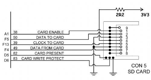
For the purposes of testing, Pins PIC pins 82 and 83 (D5 & D6) can be grounded providing your SD card is present. Use the SD card pin numbers Grogster provided in his very clear diagram above. I would suggest using a multimeter to buzz out the SD adapter PCB to check the external pin connections to the SD card socket as they may not be directly aligned. The left hand side of this diagram shows the PIC32 pin numbers and the pin names (names should reflect what the UBW32 interface pins are labelled) Regards, Mick EDIT*** Grogsters and my connection diagramss differ in the CARD ENABLE line (mine shows A1, Grogs shows A0) Try both but I think mine (A1) is correct. Mik Mick's uMite Stuff can be found >>> HERE (Kindly hosted by Dontronics) <<< |
||||
| circuit Senior Member Joined: 10/01/2016 Location: United KingdomPosts: 299 |
Mik, thank you. Yes, in fact although I checked out Grogster's pins against my schematic, I had failed to notice the A0/A1 discrepancy. My connection was mapped to A1. I have checked the UBW32 schematic and I note that A0 emerges at UBW Leg7 and is mapped to "Pin20" in MMBasic. Therefore I agree that CARD ENABLE should be connected to A0. I had thought of tracing pins to board connections on the SparkFun SD board, but the problem is that the actual internal SD card connection wipers are not easily accessed and they do not appear to run directly in line out of the connector; I think that the pins leading out of the surface-mount connector are wired into the switches (card detect, write protect) and are interposed with connectors to the SD card wipers. Therefore, without actually stripping off the metal card casing, tracing with a multimeter is not easily feasible. Once again, I am very grateful for the time everyone is spending on assisting me through what should be a very simple and straightforward connection. Circuit. |
||||
| bigmik Guru Joined: 20/06/2011 Location: AustraliaPosts: 2979 |
Hi circuit, Of course the schematic of the Sparkfun module is on their web site.. Go to the link you posted and click on schematic... I would post the link but I am on my iPad and it is not as easy as when on my PC. Regards, Mick Ps you said A0 was correct I think you meant A0 is NOT correct. Mik Mick's uMite Stuff can be found >>> HERE (Kindly hosted by Dontronics) <<< |
||||
| cosmic frog Guru Joined: 09/02/2012 Location: United KingdomPosts: 307 |
Also note that the 2R2 resistor has been known to cause problems on some setups and may need 'bridging out'. Some keyboards can also cause problems with the function of the SD card also. Dave. |
||||
| Grogster Admin Group Joined: 31/12/2012 Location: New ZealandPosts: 9918 |
@ Mik - have you had a canine tragedy?  Your avatar has changed..... Your avatar has changed.....
@ cosmic frog - Interesting. I have found the opposite. Without the 2R2, inserting the SD card to a running CMM or E64 module will cause the system to reboot. I guess there is some kind of short but significant surge when you do that with the system powered up. The 2R2 always fixes that problem - for me. Smoke makes things work. When the smoke gets out, it stops! |
||||
| Page 1 of 2 |
|||||
| The Back Shed's forum code is written, and hosted, in Australia. | © JAQ Software 2026 |
