
|
|
Forum Index : Microcontroller and PC projects : uM2(+): Wifi replaces USB for console?
| Page 1 of 4 |
|||||
| Author | Message | ||||
| matherp Guru Joined: 11/12/2012 Location: United KingdomPosts: 11512 |
There are so many uses of the ESP8266 and today I thought I'd try using it as a simple Wifi to UART converter. There is some nicely written code freely available here . I just downloaded the binaries (no need to install the Arduino IDE or compile anything) and used the NodeMCU Flasher 64-bit windows program to load it up. There is also a 32-bit version available Depending on what you have been running on your ESP8266 it is worth completely erasing it before loading new firmware. This program has the option to do that. I found that the program wouldn't overwrite ESP8266 Basic without completely erasing first. Once you have downloaded the Wifi/Uart binary run the NodeMCU Flasher and set up the three bits of the binaries to be flashed on the "Config" tab 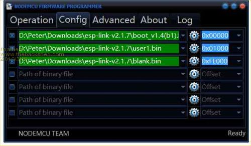
The instructions on Github are quite good but miss the issue of where to load "Blank.bin". On a 1MB ESP load it to 0xFE000. On a 2MB version use 0x1FE000. On a 4MB one use 0x3FE000. I haven't tried using one of the early 512MB ESP8266. Set the Flash size on the "Advanced" tab. The ESP8266 will automatically adjust to the baudrate set but 115200 works well 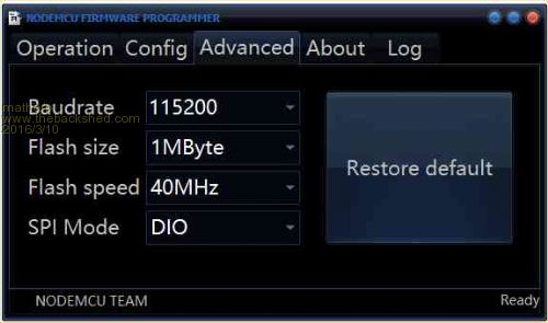
Finally, go back to the "Operation" tab and click "Flash" As always when flashing an ESP8266 GPIO0 needs to be connected to GND. I also find that after clicking "Flash" then briefly grounding the RESET pin on the ESP8266 will result in 100% success in flashing. 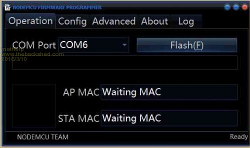
Once the ESP is programmed follow the instructions on github to configure it for your wifi network. Remember to remove the GND on GPIO0 and reset the ESP. Then use your favourite console program (it is MMEDit I assume) and create a Telnet connection to the IP address that the ESP software reported. I then create a fixed IP allocation for the device's MAC address on the router so I know it will always be on the same address. 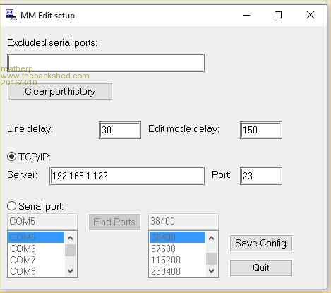
From then on you have normal console access to the Micromite as though it was wired via USB - excellent  . Programs download from MMEdit just as normal allowing easy remote program update. . Programs download from MMEdit just as normal allowing easy remote program update.
IMPORTANT the github code sets the ESP8266 to run the UART at 115200 baud so you must use OPTION BAUDRATE 115200 on the Micromite before connecting via Telnet |
||||
| MikeO Senior Member Joined: 11/09/2011 Location: AustraliaPosts: 275 |
Totally agree with Matherp. I have been using this program very successfully for some time, see my earlier post. One caveat, whereas MMEdit chat communicates fine I usually use Teraterm in conjunction with MMEdit and I could not get teraterm to work reliably in this case (I have used teraterm over TCP/IP previously ok). In my post I do refer to another Terminal program I found however and it works very successfully it even has macros and file transfer so I am still able to use Tassy Jims excellent "Crunched" file transfers. By the way if you still want to use 38000 baud you can set the serial rate in the ESP8266 programs Web page. My unit in use on my weather station. 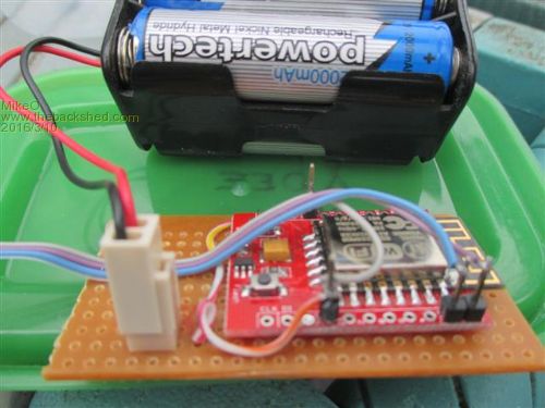
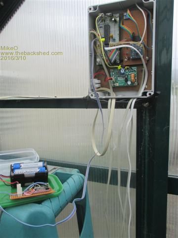
Mike Codenquilts |
||||
| Phil23 Guru Joined: 27/03/2016 Location: AustraliaPosts: 1667 |
Am I correct in assuming this would be a suitable device? ESP8266 Serial WIFI Wireless Transceiver Module And this? It seems to be more of a development board, but the seller has really good delivery time, so might suit me, but not if it won't do the job. NodeMcu Lua V3 WIFI Networking development board Based ESP8266 Haven't looked at the China suppliers yet, but they generally take 2 or 3 weeks to deliver & would prefer something I can order today & receive later in the week. Thanks. |
||||
| bigfix Senior Member Joined: 20/02/2014 Location: AustriaPosts: 130 |
Nodemcu LUA has an integrated 340 type USB to TTL serial converter You need native TTL serial to connect to the MMite |
||||
| matherp Guru Joined: 11/12/2012 Location: United KingdomPosts: 11512 |
Yes that is what I am using |
||||
| MikeO Senior Member Joined: 11/09/2011 Location: AustraliaPosts: 275 |
@ Phil23 I get mine at here , good delivery, prices and LOCAL. Mike Codenquilts |
||||
| JohnS Guru Joined: 18/11/2011 Location: United KingdomPosts: 4335 |
If you're not in a hurry they come from China at about a fifth the price (and I suppose local ebay seller within days for a half/third the price). There are lots of variants, depending exactly which features you want. They're a bit power hungry when active for some uses. John |
||||
| Phil23 Guru Joined: 27/03/2016 Location: AustraliaPosts: 1667 |
Thanks Mike, Is there a specific you recommend, there seems to by a fair variety of options. As mentioned, I'd prefer to configure it separately on a PC & then connect it to the MM once setup, to avoid needing code on the MM. |
||||
| Phil23 Guru Joined: 27/03/2016 Location: AustraliaPosts: 1667 |
Just trying to get past first base with the device I received today. Got it connected to a FTDI device. It's powered with 3.3 Volts, TX & RX pins swapped. Notice it's marked for 3.6 to 5.5 volts, but tried 5 Volts too. Was expecting to be able to see a response to the AT commands in Teraterm, but nothing. Tried a range of Baud rates in the Terminal. Do they need to be set from device manager? Thanks Edit:- I also have a CP2102 device I haven't used yet. |
||||
| JohnS Guru Joined: 18/11/2011 Location: United KingdomPosts: 4335 |
Please post details of what you bought (a link, preferably) as some come preprogrammed with such as Lua so don't do AT commands. (You can reflash.) John |
||||
disco4now Guru Joined: 18/12/2014 Location: AustraliaPosts: 1127 |
If I remember back one of the things you need is to set your terminal program to use CR+LF when transmitting. (setup--> terminal on teraterm.) No CR+LF at the end and it wont talk to you. I just tried my latest one and it's settings seem to be 115200 baud, 8 bit N parity, 1 stop. I remember some of the early ones I got where at 9600 initially. Regards Gerry F4 H7FotSF4xGT |
||||
| matherp Guru Joined: 11/12/2012 Location: United KingdomPosts: 11512 |
Are you also pulling the CH-PD pin high? this is needed to keep the module out of reset |
||||
| Phil23 Guru Joined: 27/03/2016 Location: AustraliaPosts: 1667 |
Opps, It was the HC-05 Bluetooth modules that arrived today, forgot I ordered them as well. Still they would be accessible via Terterm to configure I'd presume? Bluetooth Modules The ESP8266 I ordered is It's been a long day..... |
||||
| JohnS Guru Joined: 18/11/2011 Location: United KingdomPosts: 4335 |
They look like ESP-01 (of the original kind so probably 4Mb serial flash). Did you connect power (Vcc & Gnd), RX & Tx, and tie CH_PD (aka CHIP_EN) to Vcc? Beware - I'm not sure they can actually stand 5V but hopefully yours can. (In case you buy more they can be a quarter that price and have double the flash.) 115200 8N1 should be OK and you need Rx/Tx swapped. Mostly they seem to need an AT command (e.g. AT+RST) with both CR and LF. If that doesn't work then I suspect they're pre-programmed with other code. You can reflash them. John |
||||
| matherp Guru Joined: 11/12/2012 Location: United KingdomPosts: 11512 |
If the PCB is blue it will almost certainly be 4Mbit (512Kbyte). I haven't tested the code on this version. The black PCBs in the same form factor are 8Mbit (1Mbyte). These are the ones I use. |
||||
| JohnS Guru Joined: 18/11/2011 Location: United KingdomPosts: 4335 |
I agree - I have both. I've not needed the extra space - yet - but they're so cheap... Oh - power: they need considerably more than I expected! John |
||||
| Phil23 Guru Joined: 27/03/2016 Location: AustraliaPosts: 1667 |
Just trying to flash one of these. Not sure how to Identify the flash size. Anyone help? Thanks Edit:- At the risk of bricking it I've tried flashing it a 1Mbyte, but doesn't seem to finish. The programmer constantly flashes up:- require("wifi") require("gpio") connect.world() Tried to run ESP_Basic_Flasher.exe but it returns an error when I try to connect to com10:, error:espcomm_open failed. |
||||
| matherp Guru Joined: 11/12/2012 Location: United KingdomPosts: 11512 |
If your PCB is black then 1MB is correct if it is blue then it is 512kB. If it is blue try loading blank.bin to 0x7E000 Make sure your wiring of the module is correct - see here I also find that after clicking "Flash" then briefly grounding the RESET pin on the ESP8266 will result in 100% success in flashing. |
||||
| Phil23 Guru Joined: 27/03/2016 Location: AustraliaPosts: 1667 |
Still having no luck with this. Searched & read till my eyes are falling out. Connected to a CP2102. Appears as Com10: & have set it to 115k baud. Powered with 3.3 volts. TX & RX pins crossed. CH_PD pulled high to 3.3v as mentioned elsewhere here. Tried momentarily grounding reset pin as mentioned. When I hit Flash, I get TX & RX activity on the CP2102 and a blue led flashing rapidly on the ESP8266. After a period of time, The programmer displays these messages in a slow loop:- require("wifi") require("gpio") connect.world() LED activity on the devices remains unchanged. If I quit the programmer:- I can see a Wifi point called "AI-THINKER-E10e07" as an available network. I can connect to it & it provides my laptop with an IP address of 192.168.4.2 with a Gateway of 192.168.4.1. If I try & open 192.168.4.1 in a browser & don't get anything. Also if I try & run ESP_Basic_Flash.exe I get:- 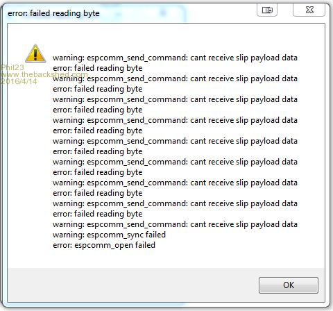
Totally frustrating, having spent 30 years in IT, something that seems to be a handicap at times. Cheers. Edit:- I do see a little activity frm the Blue LED on the ESP8266 when I attempt to run the Basic flasher. |
||||
| matherp Guru Joined: 11/12/2012 Location: United KingdomPosts: 11512 |
You do have GPIO0 pulled low when programming and the remove the connection and reset afterwards? Are you powering from the CP2102? That won't work - you need a really meaty 3.3V supply as the ESP8266 takes serious power intermittently when transmitting on wifi |
||||
| Page 1 of 4 |
|||||
| The Back Shed's forum code is written, and hosted, in Australia. | © JAQ Software 2026 |
