Notice. New forum software under development. It's going to miss a few functions and look a bit ugly for a while, but I'm working on it full time now as the old forum was too unstable. Couple days, all good. If you notice any issues, please contact me.
Tinker Guru Joined: 07/11/2007 Location: AustraliaPosts: 1904
Posted: 02:30am 05 Nov 2016
Copy link to clipboard
Print this post
The one you mention above, across the secondary before anything else connects to it.
I use pin 6 startup/ shut down as per EGS002 board.
These boards are quite cheap, two of them cost me $11.00 and I doubt oztules board could be had cheaper fully populated.
But, the EGS002 board has to be modified. If I were you I'd order one and by the time you get it I would have finished testing and published the mods plus the method of turning the inverter on/ off with that board.
I still cant figure out why you have a poor shape sine wave while oztules gets good results with an identical board. The little toroid I use in my test rig came from a junked 48V/ 1.2Kw Latronics LS inverter. I just took off a few turns of the secondary as posted above somewhere.Klaus
oztules Guru Joined: 26/07/2007 Location: AustraliaPosts: 1686
Posted: 10:54am 05 Nov 2016
Copy link to clipboard
Print this post
Something seems wrong Mad.
If you have two pictures, and they are the same point but reversed leads, the pics should have been exactly the same except for sign.. if you out them together you get a complete sine wave with no gaps.
I can't explain how that can happen unless the scan rate in the cro is affecting it somehow, either beating against the signal, or against interference in the setup on the bench...... somehow it is assymetrical just from reversing polarity. In short, I have no idea.
I do know that from talking to you, you had it running at 1700-1800 watts or more for 30 mins, and the heat sink only went up 3 degrees or so...... that tells me the waveform is very good.. a poor waveform means heat as a rule... and 3C over ambient for 30 mins at near 2kw is not my idea of poor form... and to rub it in, only 2 fets per bridge........ amazing really.
Tinker, I would have thought a few more watts were available for a single fet/channel before temp degradation got hold.... but gee the waveform was perfect.... but see comment above to Mad. I guess we need to see the spwm wave to see the heat problems, not the output so much on reflection.
Your unit takes up a fair amount of realestate... a power designer would topple into the afterlife looking at that.. reminds me of mine
I have not gone further with the current shut down for transients as time has not been in my favour... but will get there..... but it performs so wel, that I have not been encouraged to get onto it... but I should.. example next....
Units out in the field are performing flawlessly, and the one spread across the bench ( previous picture of wave form I think somewhere here) was running the 5hp single phase motor in the lathe yesterday... most of the day. Start up was zippy with no sign of struggle.... and 5hp single phase motor is quite a load to get going with a cold gearbox full of oil too....once running the lathe ( 5hp motor) idles at 1.5kw-1.8kw
If I run it on grid, it tends to blow the 20 amp o/loads if it does not get to speed fast enough.( perhaps 1 in 4 starts) so thats about 60a @ 240v to blow that..in 10 seconds...... the surge should be 15amps x at least 6 so 90amps I guess.. probably more for an instant.... which lines up fair with the o/load characteristics... usually takes 4-5 seconds or 80-90amps... cold oil
A note on breakers...... they don't blow at rated current. At rated current they should hold for 10000 seconds, at 20x rated current they last for 1 cycle@50hz... and at say 7 x rated current will last 2 seconds and 4 times rating will yield 5 seconds etc etc. So in this case will hold 90 amps @ 240v for nearly 5 seconds
Those kinds of figures make my head spin, but the inverters will do it... simply amazing to me.
I am hoping we can have enough folks doing this that we can finally see what needs to be different to make the changes to the wave form. I make them all the same, so nothing changes..... but the myriads of different designs out there must tell us something sooner or later. It has to be in the drive line ... but pwm is more complex than that... could be anything really.
............oztulesEdited by oztules 2016-11-06Village idiot...or... just another hack out of his depth
Madness Guru Joined: 08/10/2011 Location: AustraliaPosts: 2498
Posted: 11:14am 05 Nov 2016
Copy link to clipboard
Print this post
Hi Oztules,
I have no doubt you have it working so well and there have been others on the forums saying the same, somehow I am f@#$@ing it up.
With increased load the waveform gets very distorted, so I don't believe it is just a CRO issue. I am working on getting everything into it's box ATM, as I see elsewhere you mentioned that made a difference, It seems there is a slight timing issue, the wave form between the choke and the transformer has 2 waves connected and the next 2 have a time gap. All going to plan (which it probably won't) I will have it all in the box today, first I am making the mount for it so I can assemble it in situ. Otherwise I would have to use an endless chain to hoist it up.
Yesterday was stinking hot and it is still spring, would be nice to get this working before winter as I am wanting it to run AC.Edited by Madness 2016-11-06There are only 10 types of people in the world: those who understand binary, and those who don't.
oztules Guru Joined: 26/07/2007 Location: AustraliaPosts: 1686
Posted: 03:12pm 05 Nov 2016
Copy link to clipboard
Print this post
A couple of pages back shows what a mess this unit is... and yet good wave @ 4kw, Tinkers ditto.... so it needs to be solved before you have it all tied up in the box I suspect.
........oztules
Village idiot...or... just another hack out of his depth
Tinker Guru Joined: 07/11/2007 Location: AustraliaPosts: 1904
Posted: 12:43am 06 Nov 2016
Copy link to clipboard
Print this post
More observations:
That large C core choke filter I pictured a while ago seems a bad idea. The little driver board shuts down when this filter is connected.
So, please disregard everything I wrote about that thing.
I was not game today to push my little 1Mosfet per leg inverter past 500W. It runs very well then, nice soft start and steady output voltage. I do not have a frequency meter but looking at the CRO graduations it appears the output runs at ~52Hz. The EGS002 is set to 50Hz. Is that reasonable?
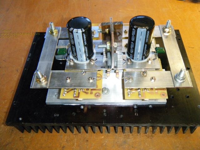
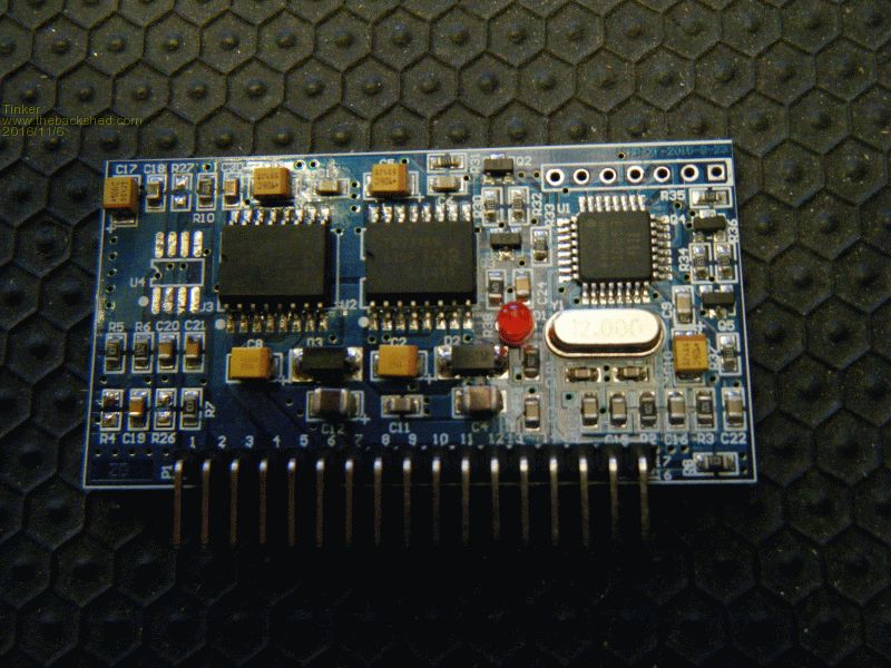
Here is a close up of the general layout.
So there is nothing wrong with that since the unit works fine.
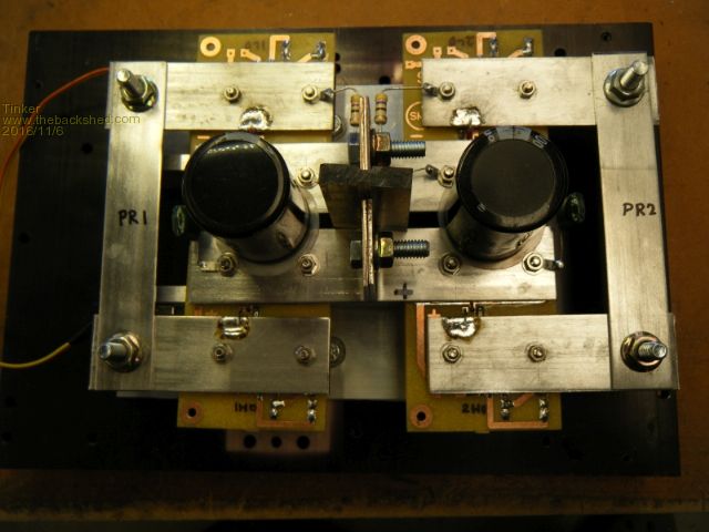
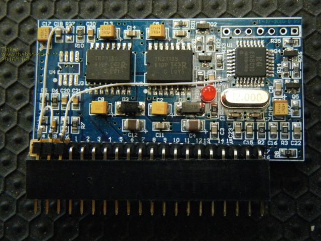
Looking at the wired up inverter:
I deliberately left the leads to the gates long to see if there are noise issues. The leads are 300mm long to *each* of the gates. There are no long and short leads (like longer & shorter gate drive tracks on some PCB's) so the gate drive signals take identical times to get there. I'm not sure if this is a big deal but it works for me.
The copper busbar track idea works well, the only bugbear is the difficulty to solder to them (they suck all the heat away and require a *huge* soldering iron). So I already have the drain Mosfet lead clamped, clamping the source lead also only requires a small mod to my PCB.
The EGS002 modifications come in my next post but I will mention now:
Blowing up the Mosfets also blows the EGS002 driver board so anybody experimenting with that driver board would do well do order several (at a little under $6.- each from ebay).
Regarding the comments on oscilloscope traces above, I measured mine with an isolated CRO at the 240V side of the little voltage sensing transformer. 10:1 probe, tip to one transformer terminal and earth lead to the other.Klaus
Tinker Guru Joined: 07/11/2007 Location: AustraliaPosts: 1904
Posted: 01:10am 06 Nov 2016
Copy link to clipboard
Print this post
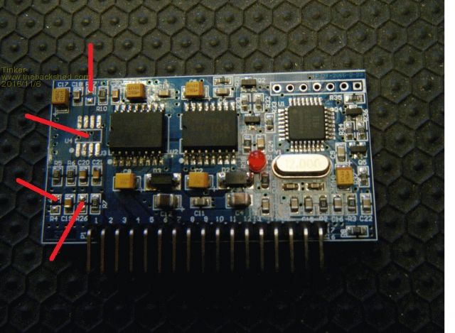
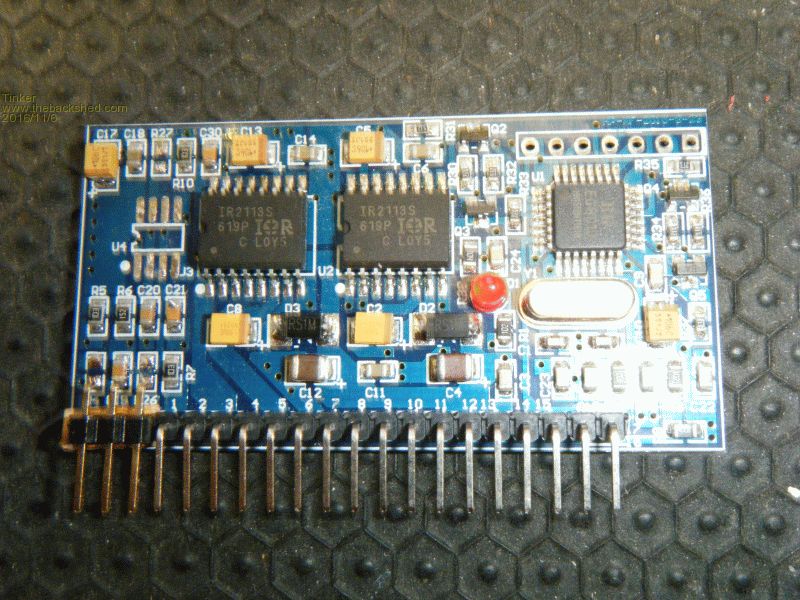
EGS002 driver board modifications.
First a few components need to be removed:
R27 was already missing on my boards. U4, R4 and R26 still require removal.
I do not own any fancy SMD unsoldering equipment so here is how I removed these items:
I had two old chisel type soldering iron tips which I cut short (to make a bigger diameter stump) and on one filed a wider chisel point. This was now wide enough to bridge all 4 leads of one side of U4.
Then I inserted a scalpel blade under U2 with a lifting action while all 4 leads were heated by the wider tip. So one side of the IC easily lifted off the board. Grabbing the IC body with tweezers the other 4 legs were unsoldered, easy peasy .
For the SMD resistors I filed a notch in the other cut down iron tip, just wide enough to straddle the component. Heating both sides at once and swiping the part off takes less than 1/2 second with no damage to the board.
I cleaned the solder pads with a narrow solder wick and inspeccted everything under a big magnifying glass to check for solder bridges.
Next came converting the 17 pin header to a 20 pin header.
I cut a header strip down to 3 pins and made a little 2mm thick wood spacer to glue the extra pins in line with the existing 17 pins.
I named those pins A,B,&C from left to right as they are ahead of pin 1. The letters correspond to the ones on my schematic.
Please disregard all other schematics of this board that I had posted here before. This one works for me.Klaus
oztules Guru Joined: 26/07/2007 Location: AustraliaPosts: 1686
Posted: 07:00am 06 Nov 2016
Copy link to clipboard
Print this post
High side snubbers missing?.... may become unstable at higher power if not used.
will have to try the current shut off later on when I get a chance.
SMD have fine legs on their ic's... so I use a razor blade and simply cut the leads from the package... then remove the legs. quick, and no excess heat needed.... so easy for the 8010 and the 2110 if you want too.
I would expect it to run at 50hz..not 52hz That should be perfectly stable.... having said that I have not measured it either.. and don't trust my scope to be useful at all... however I have a signal generator that will help in this regard.
........oztulesEdited by oztules 2016-11-07Village idiot...or... just another hack out of his depth
Tinker Guru Joined: 07/11/2007 Location: AustraliaPosts: 1904
Posted: 11:54pm 06 Nov 2016
Copy link to clipboard
Print this post
Thanks for your input oztules.
"high side snubbers missing"?? There is a snubber (47R + 0.01uF/250VAC) at each end of the primary - see drawing. So one at the hi side and one at the lo side. Am I missing something here, please explain? Definitely do not want any instabilities at power.
Ha, I did not think the SMD IC legs can be cut with a blade. There's no way a side cutter gets to them. Thanks for the hint.
Re that 50Hz comment, I just remembered the little display I bought with my first EGS002 board does have a frequency readout. I just have to solder in a socket to plug the display in temporarily. Its digits are way too small for a permanent installation.Klaus
oztules Guru Joined: 26/07/2007 Location: AustraliaPosts: 1686
Posted: 12:23am 07 Nov 2016
Copy link to clipboard
Print this post
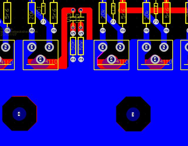
easy way for me is this.... three screen shots of the first duo of snubbers from primary to ground (-) and then primary to b+... then a far away shot showing position of both... there are 4 (four) snubber newtorks I use.... chack your PJ boards... they are the same.
First neg to primary/s
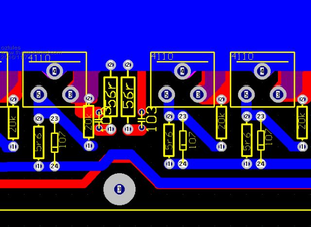
Then B+ snubbers
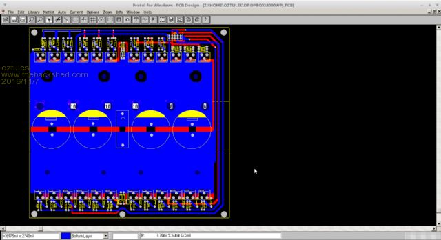
Pic to show position of other shots
Ignore the 56 and 50 r.... they are all 50r on the snubbers, but I am not particular with the drawing from the looks....
.......oztulesEdited by oztules 2016-11-08Village idiot...or... just another hack out of his depth
Tinker Guru Joined: 07/11/2007 Location: AustraliaPosts: 1904
Posted: 12:25am 07 Nov 2016
Copy link to clipboard
Print this post
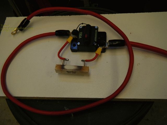
At the risk of mentioning the obvious, here is something I found very useful when testing my inverter:
Its simply a marine type DC circuit breaker bypassed with a 33R/20W resistor. The discolouring of this resistors shows it already has been useful , I salvaged it from the main board of the 3Kw Aerosharp.
I just wish I used that at the beginning, would have saved me a few Mosfet chips.
Following is how I test now.
Switch everything off (C/Breaker & inverter SW), no load connected.
Connect DC leads to battery bank, there might be a tiny spark upon making contact.
Measure the voltage at the main capacitor rails. It should increase to almost battery level as the caps charge up.
If this voltage settles more than 0.5V lower from the battery bank voltage, disconnect immediately, something is drawing too much current - investigate.
If cap rail voltage is OK connect a CRO to the 240V winding and switch on the inverter ON switch. The wave form should soft start and settle steady with no distortions.
If OK continue, if not switch off and investigate.
Close the DC C/Breaker (this shorts the 33R resistor), the wave form should remain steady. Apply a small load - 100W or so, if everything looks OK connect bigger loads up to the expected limit.
If it was wired up as in the above diagram and it suddenly shuts down at a bigger load the current sense potentiometer may be set too low and needs adjustment then.
Klaus
Tinker Guru Joined: 07/11/2007 Location: AustraliaPosts: 1904
Posted: 11:28pm 12 Nov 2016
Copy link to clipboard
Print this post
So I'm fishing for more clues .
Does it make a difference with the sequence of applying power to the inverter?
Today I switched it on with that 33 Ohm resistor (shown above) in series with the positive lead.
Everything looked fine and soft started nicely. Power draw was about 0.5A on standby.
Left it running and then shorted that resistor and the inverter immediately had the dreaded "flash/bang" syndrome.
Should I have switched it off first, short that resistor and then turn the power switch to 'ON'?
Oztules, thanks for the heads up re the snubbers, I have arranged them this way on the full complement inverter but have not yet been game to switch it on. First I'll have to get my small test inverter to work perfectly.
And another question: on The EGS002 board they have a kind of transistor inhibit circuit between the EG1810 SPWMOUT lines and the HIN/LIN at the IR2110S drivers. You don't have that on your driver board, why?
Thanks. Klaus
Madness Guru Joined: 08/10/2011 Location: AustraliaPosts: 2498
Posted: 01:23am 13 Nov 2016
Copy link to clipboard
Print this post
Hi Klause,
I have not done as above, I charge the caps and then turn on the breaker. Never had it go bang at the point of turning on the breaker. (lots of other ways I know how to make it go bang though)There are only 10 types of people in the world: those who understand binary, and those who don't.
oztules Guru Joined: 26/07/2007 Location: AustraliaPosts: 1686
Posted: 02:00am 13 Nov 2016
Copy link to clipboard
Print this post
"And another question: on The EGS002 board they have a kind of transistor inhibit circuit between the EG1810 SPWMOUT lines and the HIN/LIN at the IR2110S drivers. You don't have that on your driver board, why? "
Simply put..... lazy. I figured that it would be very problematic to have that sort of problem... if so it was terminal anyway. The cross talk can only really happen if it has all gone to hell anyway.
You will note that the 002 board you are using... has not saved you with these things there, and I have had no problem with the 8010 board without them.,.. so have run with the simple version. If you look at the 8010 data sheet they mostly don't use then either.
Startup: Once I used the 120R and the cap, start up has never been a problem howsoever done. The only proviso is not to allow it to take too long to get up to voltage, or the uvlo internal stuff locks up...no damage, just goes inert.
It seems to start fine under load, no load, start without turn off switch, start with turn off switch..... start by splatting the battery lead with it turned on as well All work fine.... turn of the same, break battery line, or turn off by switch. still all good.
I installed a hot water unit the other day out on one of the outer islands with one of these units.... been a few months now ( July?), and I forgot when I turned it on, as the water pump, coffee machine, hot water and who knows what else all tried to start up at the same time on soft start... gauge mentioned 7.5kw or more.... failed to get going, so it retried almost immediately.... failed at 8kw on the gauge... then it got it third time...... I was in a cold sweat I'm sure, as I didn't even turn it off as I assumed the current sense would kill it...I was frozen...... but it just powered away.... don't know what the peaks would have been, but they would have been very high, those gauges are very slow... 1 or 2 seconds behind the action.
No idea why the current sense didn't go into the 16 second stuff, it just tried, tried, then worked in a few seconds.
So they start up in any condition from the looks.
I am troubled by your experiences.
I have not used the scr current stopper in the real world as yet... too busy
.........oztulesEdited by oztules 2016-11-14Village idiot...or... just another hack out of his depth
Tinker Guru Joined: 07/11/2007 Location: AustraliaPosts: 1904
Posted: 08:17pm 13 Nov 2016
Copy link to clipboard
Print this post
Thanks oztules, I think I will join your club of 002 board disbelievers. These boards appear to loose their AC voltage sensing (and hence the soft start) after the flash/bang of a Mosfet melt down.
Two of the busted boards now power up with the under voltage LED flashing sequence, the other 2 show visible damage (craters) on the chip surfaces. While I still have two more 002 boards on order and 4 busted ones on my bench, time has come to consider there is something inherently weak with them.
The major parts work as you have proven to us all so I will endeavor to reverse engineer your board to make it a plug in replacement for the DIL socket my 002 board plugged into.
This is easier for me as the power/current sensing parts and the 12/5V & fan control circuit are on a little mother board. I like to keep all arranged that way.
Did you re use that 12MHz Xtal from the 002 board? Yours looks just like it.Klaus
oztules Guru Joined: 26/07/2007 Location: AustraliaPosts: 1686
Posted: 10:44pm 13 Nov 2016
Copy link to clipboard
Print this post
Guilty... I did use the crystals from the dead 002 until my new ones arrived.
002 was still a good board, no problems unless I created them ( and I did with the power supply).... some thing else is causing the instability I think.
...........oztulesVillage idiot...or... just another hack out of his depth
Tinker Guru Joined: 07/11/2007 Location: AustraliaPosts: 1904
Posted: 01:57am 15 Nov 2016
Copy link to clipboard
Print this post
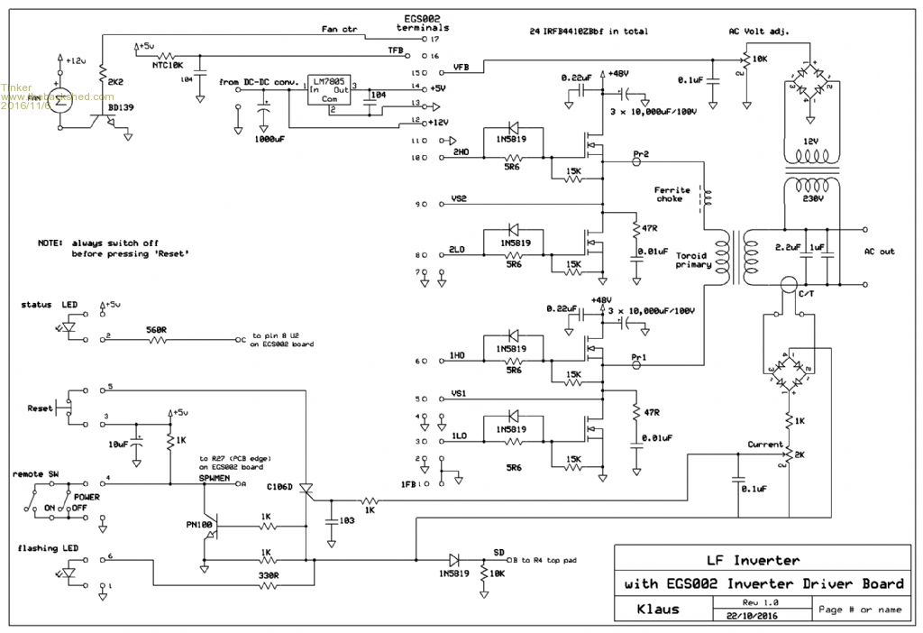
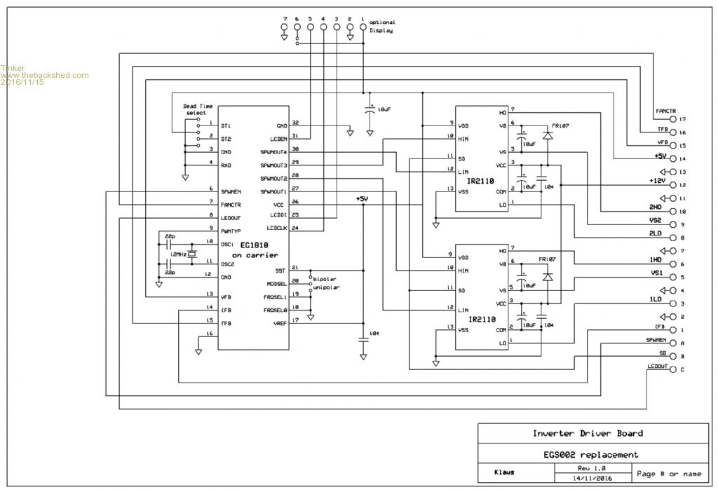
Being fed up with EGS002 boards that malfunction far too easily I have drawn up my own. It is a direct plug in replacement but with less bells & whistles. The info for it comes from oztules driver board and data sheet perusal.
But I would like a thorough checking by somebody else, its too easy for me to make mistakes. So, here is the schematic:
This is to be used in conjunction with the little mother board, the schematic of which I posted earlier.
Once it is confirmed that the schematic is OK I'll proceed to lay out a simple single sided PCB for it.Klaus
Tinker Guru Joined: 07/11/2007 Location: AustraliaPosts: 1904
Posted: 12:18am 04 Dec 2016
Copy link to clipboard
Print this post
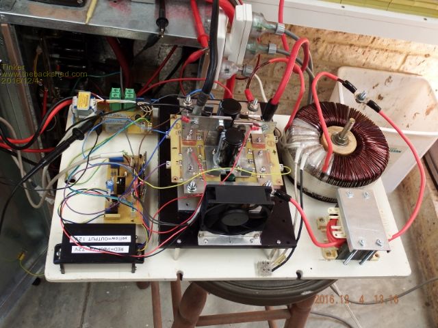
Today I managed to pass my target of 1KW load from the 4 Mosfet test inverter. I stopped increasing the load at 1150W load, the little toroid I'm using is from a 1200W Latronics LS inverter and most likely not rated for continuous 1200W.
After a while on 1150W the toroid reached 80 degree on the primary winding, I then reduced the load to around 600W, giving the winding a respite. It was running much cooler then.
The heatsink did not get warm at all, barely above ambient temperature and the little fan never switched on.
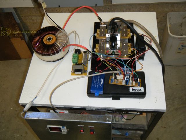
Here is the test set up:
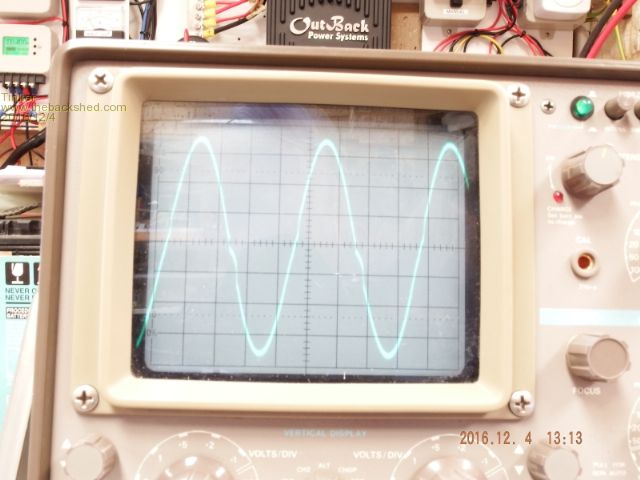
And here is the oscilloscope trace at 1150W:
The little wiggle on the down curve almost disappears at no load. I took that picture with the camera on a tripod and set the scene select to "fireworks". Seems to capture the whole trace but my ambient lighting was still a little too bright.
So what is different now? Well, the big break through came when I reduced the PCB tracks between the gate and its resistor/diode to virtually nothing. These parts now cannot be closer located to the gate pin.
Also, I gave up with the IRFB4410Z mosfets, they kept blowing up at >600W loads. They were also not ideal with regard to leg size and spacing. I cannot understand why others even bother with TO220 devices on a high power inverter.
I now use TO-247 Mosfets (HY4008W/A). Only four per bridge leg will be used in the full size inverter, four of these having a larger current rating than the 6 x 4410 that others use.
They are no more expensive for a similar current, buying 32 x HY4008 is only slightly dearer than buying 50 x 4410's - double the required number to allow matching the on resistance.
With regard to on resistance, the HY4008 I got from Ali express were under 4mOhm, mostly around 3.5mOhm. Only two were a little over 4mOhm.
The only thing to note with these TO-247 chips is their odd (5.44mm) leg spacing which does not suit the snap in position grid of the simple PCB layout program I use. I could, however, tweak the pad location by disabling the snap in position feature.
The above test was with my last EGS002 board driving the Mosfets, there are 5 junked EGS002 boards lying on my bench now . These boards are not very robust IMO.
I am still progressing with the design of my EGS002 replacement board, its not as easy as it seems. Oztules was either very knowledgeable or lucky when he got his board working first time. Track layout appears to make a big difference but I'm close now, waiting for some more driver chips.
Klaus
Madness Guru Joined: 08/10/2011 Location: AustraliaPosts: 2498
Posted: 01:23am 04 Dec 2016
Copy link to clipboard
Print this post
Oz certainly has something on his side that others of us seem to be wanting for.
Good to hear you have had a win with the gate modifications. I have revised my design again by reducing the pad size on the gates and the pins where there is no current flow. I have etched the board but have been busy installing an air conditioner. The board I am using at the moment has TO220 IRFB4110 MOSFETs and I got 8 KW out of it for 30 minutes with no issue. However I am only using them as they are cheaper than the TO247 version, when I am happy with how it is performing I will start using TO247 IRFP4110's I have. The AC I just installed can draw up to 3.55 KW, although it was down to under 1500W this afternoon when it was a little cooler. So I do need the Inverter to handle 4KW plus for extended periods.There are only 10 types of people in the world: those who understand binary, and those who don't.
Tinker Guru Joined: 07/11/2007 Location: AustraliaPosts: 1904
Posted: 03:43am 04 Dec 2016
Copy link to clipboard
Print this post
I just looked them up on ebay. Expensive, aren't they. They have a higher voltage rating but a lower current rating than the HY4008, their quoted on resistance is also higher.
I hope I get away with the 80V rating of the HY4008, my lithium battery bank never gets over 60V so there is a decent voltage margin.
I would need much more than my 10Kw lithium battery bank to run an air conditioner outside sun charging hours. It gets hot here in Perth but there is usually a sea breeze to cool the house down after sun set.Klaus
oztules Guru Joined: 26/07/2007 Location: AustraliaPosts: 1686
Posted: 08:39am 04 Dec 2016
Copy link to clipboard
Print this post
Well Mad, you have beaten me now. I have had plenty of 8kw for 5-10 or more minutes, but never 30 mins continuous. So after some false starts, it looks like you ave it now.... your tenacity in the face of disaster is a credit to you.
Tinker, you results are looking very good too, and I hope it translates up to your monster you are going for.
I got some HY4008 for about$30/24. They measured in at 2.7MO... every one of them. I too decided that the chinese make a mess of copying the 4110 american things, but should not bother/counterfeit their own. So it seems to be. There specs are identical with all 24 of them, and the lowest I have seen for RDSon so far... 2.7 is not too shabby at all.
I don't know how well they work, as I have not made a board for them as yet... may strip a clockman board and try them on that.
The Latronics transformer seems to be a bit under done for their rating.
Tinker, how is the current regulation doing at high power shut down, I am finding slight inconsistency in the scr locking off at the moment. What works fine on one board, needs slightly different resistors on another... no idea why that could be...
.........oztulesEdited by oztules 2016-12-05Village idiot...or... just another hack out of his depth


 .
.
 .
.
 . These boards are not very robust IMO.