
|
|
Forum Index : Microcontroller and PC projects : Special "Back Shed" offer on Autotrax DEX
| Author | Message | ||||
plover Guru Joined: 18/04/2013 Location: AustraliaPosts: 302 |
I decided to spend a few minutes on the Dex Website, to see if it mentioned Linux, which I don't think is an option. However skipping through the whole page I am very impressed. Considering I spent about $2000 20 years ago I suppose it is for the earlier Protel, spending $39 US on this I a very tempted to get a copy just to put on the shelf for when I might really get back into tinkering. With a number of people on this forum getting tempted I am guessing that extra custom parts may be available even if one does not pay upgrade each year.  |
||||
bigmik Guru Joined: 20/06/2011 Location: AustraliaPosts: 2870 |
@Plover (1) Sorry, I am fairly certain that there isnt a LINUX version out there.. If you join the forum then you can ask the question, I am sure there are people out there who have Linux and can answer the question for you. I know people with MACs are using it via another `emulation??' program. @Rob, Yes my progress after the `letraset' age was DOS Based `SmartTrax ??' or something similar sounding that printed onto my dot matrix printer at 2:1 and then we reduced it photographically. Then I went into PADs then Protel AUTOTRAX (Not the same prog/author as DEX) then work bought Protel 98 for about $4k then they upgraded to Protel 99se that I used for about 10 years then I chose AUTROTRAX DEX. I chose DEX as I really didnt like the way Eagle did the schematics and the PCB section looked to be a clone of Protel 99se... It wasn't it was an entirely new learning base from Protel.. However I always hated the way Protel worked, The autorouter was brilliant though. I did find DEX a bit difficult initially but that was mainly because I do then I read the manual.. I am only scratching at the surface of DEX's capabilities and have learned basically what I want to do with it.. @Plover (2) The problem with letting it `sit on the shelf' is your 12mths update license might expire before you use it. It is well worth checking out the Video clips that show how DEX works in the hands of an expert (Iliya of course) see the videos at https://kov.com/Videos . You will find a video `How To' on just about every feature.. There is also a downloadable Manual of several 100's of pages. Kind Regards, Mick Mick's uMite Stuff can be found >>> HERE (Kindly hosted by Dontronics) <<< |
||||
| ajkw Senior Member Joined: 29/06/2011 Location: AustraliaPosts: 290 |
@plover I find that Windows 7 and hence DEX runs quite fine with VirtualBox on my Ubuntu box. Other than that, as a complete novice I knocked up a board a little while back for a project with a 20x2 LCD screen and was very happy with it. Anthony. |
||||
| austfox Newbie Joined: 05/03/2016 Location: AustraliaPosts: 18 |
Thanks for arranging the offer, much appreciated. Just paid for my copy... about to download it and give it a whirl. Steven. |
||||
| bigmik Guru Joined: 20/06/2011 Location: AustraliaPosts: 2870 |
@Steven, My Pleasure Mik Mick's uMite Stuff can be found >>> HERE (Kindly hosted by Dontronics) <<< |
||||
| MicroBlocks Guru Joined: 12/05/2012 Location: ThailandPosts: 2209 |
After viewing some of the videos i can see the value of this software package. Some of the things that are laborious to do in Diptrace you can do pretty simple. Especially dragging pins around and changing the component layout in the schematic is very useful. I did not see any samples with uses colored lines in the schematic and same colored traces in the PCB. For me that is one of the useful features i would like to keep. Microblocks. Build with logic. |
||||
| bigmik Guru Joined: 20/06/2011 Location: AustraliaPosts: 2870 |
Hi Jean, Yes DEX can do colours as you like in DipTrace, even better IMHO See this schematic of a HORN circuit for a car. 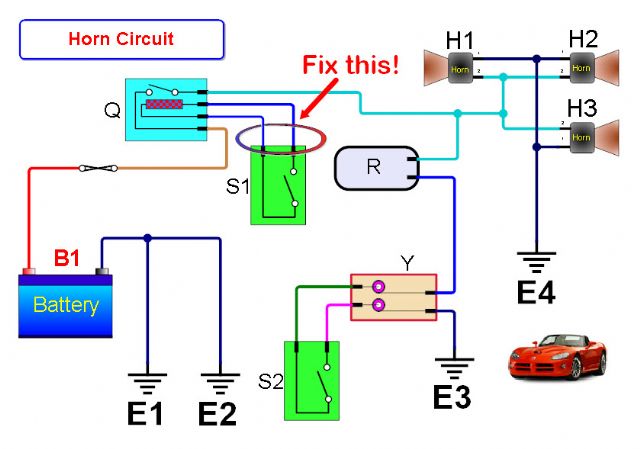
If you have joined the Autotrax DEX forum you will find this thread that I created asking that very question. Colours in Schematics Thread Regards, Mick Mick's uMite Stuff can be found >>> HERE (Kindly hosted by Dontronics) <<< |
||||
redrok Senior Member Joined: 15/09/2014 Location: United StatesPosts: 209 |
Hu bigmik;Thank you for showing me these examples. That's just what I wanted. I can see the learning curve is pretty steep though. I just got DEX and added "Catalog 1" extra parts. However, I can't find any of the uMITE parts. PIC32MX170 B nor D PIC32MX470 H nor L Where do I find them? redrok |
||||
| bigmik Guru Joined: 20/06/2011 Location: AustraliaPosts: 2870 |
Hi Redrok, They probably do not exist `yet' in the DEX world. I created quite a few libraries and included the 28pin '170, 250, and SSOP 170 footprints (feetprints??) You are welcome to use those if they are of use to you. MY Libraries are in `AUTOTRAX' directory in My `SITE' Click Here It is fairly easy to do a 470 although I have of yet not done one.. There are quite a few pin spacings for the 470 which do you want? If I get some time I will do one for you later today, or tomorrow. Mick Mick's uMite Stuff can be found >>> HERE (Kindly hosted by Dontronics) <<< |
||||
| bigmik Guru Joined: 20/06/2011 Location: AustraliaPosts: 2870 |
Hi Redrok, All, I really need to update my libraries.. I have just created a foot print for the 64pin '470H and then found I have already made one about a year ago, (but it wasnt in my online library) Anyway, Here is the new (suffix 64pin) and old one I did last July. Take your PIC (pun intended) of which ever you like. I will do a 100 pinner but there are 2 footprints 12mm and 14mm .. Which is the one we use or are people using?.. The creation of the part is easy about 4minutes to create, the typing in all the pin names is the hard part. That took me about 40 minutes.. My eyesight is not the best for reading and transcribing those pin names. 2016-04-27_032443_PIC32MX470F512H.zip Regards, Mick EDIT **** I should make the note that I TAKE NO RESPONSIBILITY for any errors in those parts I provided, hopefully the sizes are all good but I havent used them.. yet. Mik Mick's uMite Stuff can be found >>> HERE (Kindly hosted by Dontronics) <<< |
||||
| MicroBlocks Guru Joined: 12/05/2012 Location: ThailandPosts: 2209 |
Thanks Mick for checking. I registered for the forum but it i somehow not receive a confirmation mail. I also downloaded the software and that email also not arrived. Changed the email in profile and tried again, also without success. Oh well, i'll give it a few more hours as maybe it is in a queue somewhere. What would save me a ton of time is when assigning a color to a net in schematics it also appears on the PCB layout. Edit: Amazing, just posted this and now the mails arrived. Microblocks. Build with logic. |
||||
| bigmik Guru Joined: 20/06/2011 Location: AustraliaPosts: 2870 |
Hi Jean, When you select a Net either in the Schematic or the PCB all nodes on that NET will be highlighted in both the Schematic and PCB. In the case of the PCB the other NETs will DIM so that the net in question stands out.. Great for manual routing. See this screen shot 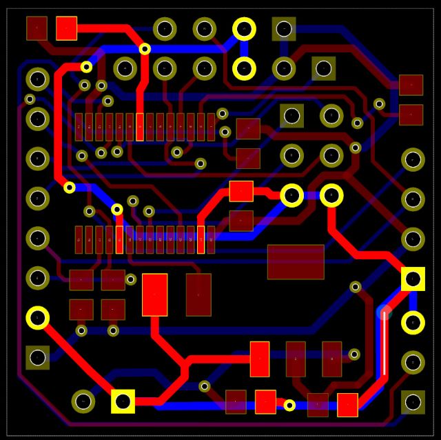
Kind Regards, Mick Mick's uMite Stuff can be found >>> HERE (Kindly hosted by Dontronics) <<< |
||||
| Geoffg Guru Joined: 06/06/2011 Location: AustraliaPosts: 3167 |
Probably the 14mm is best because it is easier to solder. Grogster has just designed a brilliant board which is a MM+ backpack for a 5" SSD1963 and that uses the 14mm chip. Geoff Geoff Graham - http://geoffg.net |
||||
| bigmik Guru Joined: 20/06/2011 Location: AustraliaPosts: 2870 |
@Jean, Attached is a PDF created by DEX showing the Schematic and I have thickened the Power and GND lines and assigned a colour to each of the nets. (5V, Vcc & GND.) Of course you can assign any net to be any thickness and colour in the schematic and in the PCB you can define a NETs thickness. In the rules you can specify a NET thickness (which is the default where possible) and a minimum Thickness and a Maximum, you can also specify a thickness of a segment(s) of track or entire track (the track between either a pad/via to another pad/via on the same side. It really is quite configurable. 2016-04-27_061044_Document.pdf Kind Regards, Mick Mick's uMite Stuff can be found >>> HERE (Kindly hosted by Dontronics) <<< |
||||
| bigmik Guru Joined: 20/06/2011 Location: AustraliaPosts: 2870 |
Thanks Geoff, I thought about it later and If the only difference is the size of the footprint it would be a simple matter to change that (there is a wizard to do the hard work) and take all of 1 minute to change so once I make one 100 pinner the next will be a piece of cake. The tough part was entering the `standard' Names, that was quite Tedious.. It also makes the Schematic part MUCH larger than it needs to be (so the Names do not cross into each other). Of course all these are configurable You can change names into Vcc, Pin(23), Gnd, SCl, SDa etc etc if you dont want the classic names then the schematic image can be resized by clicking and dragging. Of course if you want the schematic can be rearranged any way with the pins in any order... It really is quite easy to do. Kind Regards, Mick Mick's uMite Stuff can be found >>> HERE (Kindly hosted by Dontronics) <<< |
||||
| MicroBlocks Guru Joined: 12/05/2012 Location: ThailandPosts: 2209 |
One thing i did not find in AutoTRAX is the ability to use the same schematic and make 2-3 different PCB layouts. In Diptrace the link between schematic is made when creating a new PCB. Pretty easy to create another PCB linking to the same schematic. Microblocks. Build with logic. |
||||
| bigmik Guru Joined: 20/06/2011 Location: AustraliaPosts: 2870 |
Hi Jean, In Autotrax DEX the schematic is LINKED permanently with the PCB.. That makes it so much easier to know your PCB is correct as if the design rule check passes and your schematic is correct then your PCB should be. However if you want to do a different PCB layout with the same schematic just copy to a new project and UN-ROUTE all the tracks, your PCB should now show the parts connected via NET wires (rats-nest), just rearrange and resize your board and route again. Mick Mick's uMite Stuff can be found >>> HERE (Kindly hosted by Dontronics) <<< |
||||
| Geoffg Guru Joined: 06/06/2011 Location: AustraliaPosts: 3167 |
Sorry to use you as the Autotrax sales off but regarding the initial licence then renewing. If you purchased the initial licence (for $39) and do not renew for a year or two then decide to renew. Do you have to start with a new licence? I hope that is not too confusing, Geoff Geoff Graham - http://geoffg.net |
||||
| MicroBlocks Guru Joined: 12/05/2012 Location: ThailandPosts: 2209 |
Yes that would be a way, however you would then have two different schematics to maintain. It is not a deal breaker, but i happen to use that a lot as i often have 2 pcb versions of the same schematic. It is actually how i design my MicroBlocks, one with full size pinheaders and the other as an module to be used as a smd part. Microblocks. Build with logic. |
||||
| bigmik Guru Joined: 20/06/2011 Location: AustraliaPosts: 2870 |
@Geoff, Sorry I do not know the answer to that, I can ask.. As I said I am NOT a rep for them nor do I get a cut of sales or referrals etc.. In fact I have no ulterior motive except to I tried to broker a deal, that I know some have taken up on, that I felt was beneficial to TBS members. I will ask Iliya and see what he says, Kind Regards, Mick Mick's uMite Stuff can be found >>> HERE (Kindly hosted by Dontronics) <<< |
||||
