
|
|
Forum Index : Microcontroller and PC projects : Simple quad-rail PSU....
| Page 1 of 2 |
|||||
| Author | Message | ||||
Grogster Admin Group Joined: 31/12/2012 Location: New ZealandPosts: 9975 |
Hi folks. 
Here is my latest quick whip-up: A quad-rail PSU. I have often found that I need several voltages at once, and more often then not, one supply has the capability to supply a certain current, while another one does not, so I end up with a collection of PSU modules all connected with wire in a birds-nest mess on my desk. Something had to be done! 
This board uses the cheap and readily available LM2596 regulator modules. These are mass-produced, and can be had on eBay for about one buck a piece. 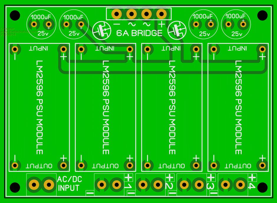
The board is designed to take up to four of these 2596 regulator modules on the one board, providing up to four separately adjustable supply voltages at currents up to 2A on each rail. Each 2596 can be adjusted between 1.25v and 35v depending on input voltage. The input voltage can be AC or DC, and the 6A SIL bridge is along the top-edge of the board to allow easy mounting of a heatsink, if you need higher total currents. There is provision for addition of extra decoupling caps on the DC side of the bridge, but these won't need to be installed if you load is low, and the input voltage is DC to start with. I recommend fitting these 1000uF caps if the input voltage is AC. The 2596 can actually do up to 3A output, but I tend to de-rate things in order to increase the lifespan of the device - heat is an electronic killer. Due to it's high efficiency, you can get up to 2A out of each rail without any heatsinking, as the module uses the bottom copper as a basic heatsink. Generally speaking, anything more then 1.5A continuous on any of these rails, and I would add a heatsink. For sporadic loads up to 3A, you can get away with no additional heatsinking at all. Heatsinks could be simple stick on ones, or a more elaborate bar-type-thing that spans all four modules at once, pressing onto each of the 2596 IC packages, as they are all in-line. I have ordered some of these boards, but if anyone is interested, let me know and I could put up a ZIP file here with the gerbers and drill data so anyone can make their own. Using the likes of Shenzhen-2U, you can get ten of these boards for US12..... Smoke makes things work. When the smoke gets out, it stops! |
||||
| Phil23 Guru Joined: 27/03/2016 Location: AustraliaPosts: 1667 |
Cool Grog, Will get you to put a few aside. Think I could put them to use. Cheers. |
||||
| hitsware Guru Joined: 23/11/2012 Location: United StatesPosts: 535 |
Amazingly you're getting the whole tamale for less than the chip ! |
||||
| MicroBlocks Guru Joined: 12/05/2012 Location: ThailandPosts: 2209 |
Most of these super cheap items use leftovers from other pcb assembly jobs. Tapes/reels often have 1000-5000 parts on them and if 80% was used, then 20% is left and basically free. Also lots of stuff end up in the bin on pick & place machines. Bags full every single day. Sorting those and using them can be profitable if your costs are low enough. If you have relationships with an assembly house or if you are family/friends of the owners then these things are possible. Other super cheap stuff use recycled parts and yes also some fake parts. If you can check the numbers on the packages you can often known the week number and year. Recycled parts can be as old as 10-20 years. Still good but obviously a shorter lifespan from the moment you buy them. If you got a recent one then you can bet it was a leftover from a previous assembly job and should get some good value out of it. The markings on the regulator that is on the picture the OP linked to is from TI and has a date code of either 2005 or 2015, fourth 6 week period. The part is either NRND (not recommended for new products) or ACTIVE as TI is notoriously bad in there markings it is impossible to know which one you have. You need a bit of luck, but for those prices it is better to order a few and accept if there is a failure. Years ago i often bought stuff on ebay, but it seems the quality gets a bit worse and you need to be more aware. Having bought a batch of 20 fake FTDI chips which brought havoc to some workshops i had cured me from buying important stuff from ebay. For hobby parts however i still use some ebay stuff, all the rest comes either direct from factory or reliable distributer. No skimping on quality and traceability for commercial product parts. @Grogster, Did you see this one: LM2596-Buck-Step-down-Power-Converter-Module-DC-4-0-40-1-3-37V-LED-Voltmeter It even has an LED volt meter. For one US buck more, not bad. Microblocks. Build with logic. |
||||
| thirsty Newbie Joined: 22/06/2016 Location: AustraliaPosts: 34 |
Zip files would be great! |
||||
| Grogster Admin Group Joined: 31/12/2012 Location: New ZealandPosts: 9975 |
UPDATE: I have cancelled this order, cos MicroBlocks drew my attention to those fabulous modules with the LED display, so I am going to redesign the board so that it can accommodate either module - the original ones or the ones with the LCD display. I have a funny feeling I even have a couple of those here I bought in just to see what they looked like, but had forgotten about until MicroBlocks reminded me about them.
Funny thing was, I was looking at voltage displays on eBay last night, thinking that it would be good to have some of those hanging off the quad-rail board so you could see the input and output voltages - time for a little redesign there. 
@ thirsty - I will still upload the ZIP file, but I will make the changes first. EDIT: I found my ones I had here, but they were bigger, so I have ordered some of those ones with the LED display on-board that MicroBlocks linked to. I will redesign the board to suit either/or. Smoke makes things work. When the smoke gets out, it stops! |
||||
| thirsty Newbie Joined: 22/06/2016 Location: AustraliaPosts: 34 |
What about one of these for each output? |
||||
| Grogster Admin Group Joined: 31/12/2012 Location: New ZealandPosts: 9975 |
Wow, yeah that is even sexier cos it has the current ability too - so cheap! 
Hmmmmmmmm - Let me have a think about this. I might end up sticking with the original modules as at the start of this thread, and having an add-on board you can plug into the first one, that will give you four of those displays - that way, those who want that, can have it, but those who don't, aren't forced into having something they don't want. This also keeps the board size under control too. Even a redesign to suit the modules MicroBlocks linked me to, would involve making the board bigger, and I definitely want to stick within 100x100, cos all PCB houses do that size nice a cheaply. Once you go above that size, the boards get expensive(compared to the price for the 100x100's). Smoke makes things work. When the smoke gets out, it stops! |
||||
| Grogster Admin Group Joined: 31/12/2012 Location: New ZealandPosts: 9975 |
OK, I have decided to stick with the board as-is, pretty much, but extending it out to 100mm horizontally. It was 91mm before, so it is only 9mm wider then before.
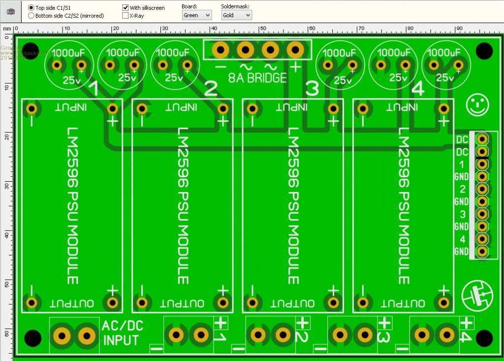
This version adds a couple more 1000uF caps for good luck. You only need to install all six if you are expecting to be running a couple of amps from each rail, although, installing them all won't hurt. For light loads, you would only need to install two or four. But I like to use as many reservoir caps as I can(within reason) for high loads.
I've also added a ten-way header on the right side, for those of us like me who like to have multi-pin plugs for several different supply voltages to cut down on space and make connection faster over having lots of terminal blocks. This header will also allow easy adding of an LED display board later for those that want it. Somewhat annoyingly, all those LED meters seem to have the current sense path in the return(negative lead) side of the load not the supply(Positive lead) as most of us would tend to wire up an ammeter. This just means you have to separate out the ground return wires and cannot use a common ground between all the rails if you want to use the displays. IE: Each rail's ground return must be electrically separate from the other rail's ground return paths. An irritation, but probably not a deal-breaker. Gerber files(RS-274X) and Excellon drill data ZIP file... Smoke makes things work. When the smoke gets out, it stops! |
||||
| Grogster Admin Group Joined: 31/12/2012 Location: New ZealandPosts: 9975 |
UPDATE: Well, the boards and new PSU modules have arrived. [Quote=Blackadder]I think the phrase rhymes with: 'Clucking Bell.'[/Quote] 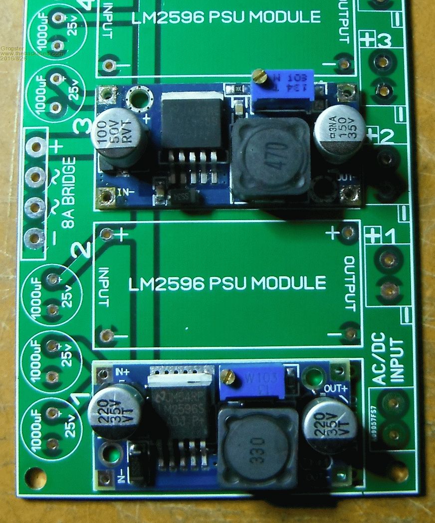
The damn new modules use a slightly different layout, and the new boards are about 2mm SHORTER then the original ones I designed the board for - curses!  
I can still use the new modules on the PCB, I just have to mount one end in the way I was planning, and run some short(but thick) wire links up to the other end. It looks messy though, and I like a neat layout. Bugger it. Smoke makes things work. When the smoke gets out, it stops! |
||||
| WhiteWizzard Guru Joined: 05/04/2013 Location: United KingdomPosts: 2991 |
Can you not just use header pins (removed from plastic housing) slightly angled inwards to keep it neat for now? |
||||
| Grogster Admin Group Joined: 31/12/2012 Location: New ZealandPosts: 9975 |
I still don't consider header pins on an angle to be neat. 
I have done it with heavy wire bent into a neat shape. I will put up a photo later. Smoke makes things work. When the smoke gets out, it stops! |
||||
| Grogster Admin Group Joined: 31/12/2012 Location: New ZealandPosts: 9975 |
Well, I will have to eat a little humble pie - WW was right, his method works fine, and it is perfectly stable, and the pin-headers only need to be angled just a little off the vertical - you would not know unless you looked really closely. 
This looks fine, so it is not the end of the world afterall. Smoke makes things work. When the smoke gets out, it stops! |
||||
| WhiteWizzard Guru Joined: 05/04/2013 Location: United KingdomPosts: 2991 |
Looks good - but would have been even neater if you had removed the header's plastic
However it does become more fiddly to construct . . . |
||||
| Grogster Admin Group Joined: 31/12/2012 Location: New ZealandPosts: 9975 |
The header plastic provides a nice even spacing off the main-board, but you were right - it looks fine.
EDIT: Photo of the unit 99% complete. No reservoir caps in place yet, as I don't have 25v ones. I will get some from Jaycar maybe even at the weekend. 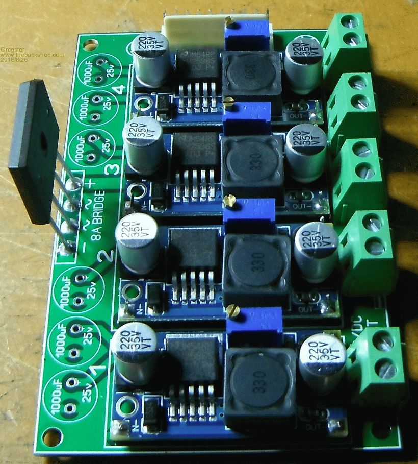
Smoke makes things work. When the smoke gets out, it stops! |
||||
| Grogster Admin Group Joined: 31/12/2012 Location: New ZealandPosts: 9975 |
UPDATE: I had a call-out in town today, so I called past Jaycar and grabbed some 1000uF 25v caps for the DC reservoir. I also dug up an old 6A tranny from the parts bin just for the purposes of setup and testing. I'll probably end up using this tranny as I have it spare, and it is doing nothing but gathering dust in the shed anyway. 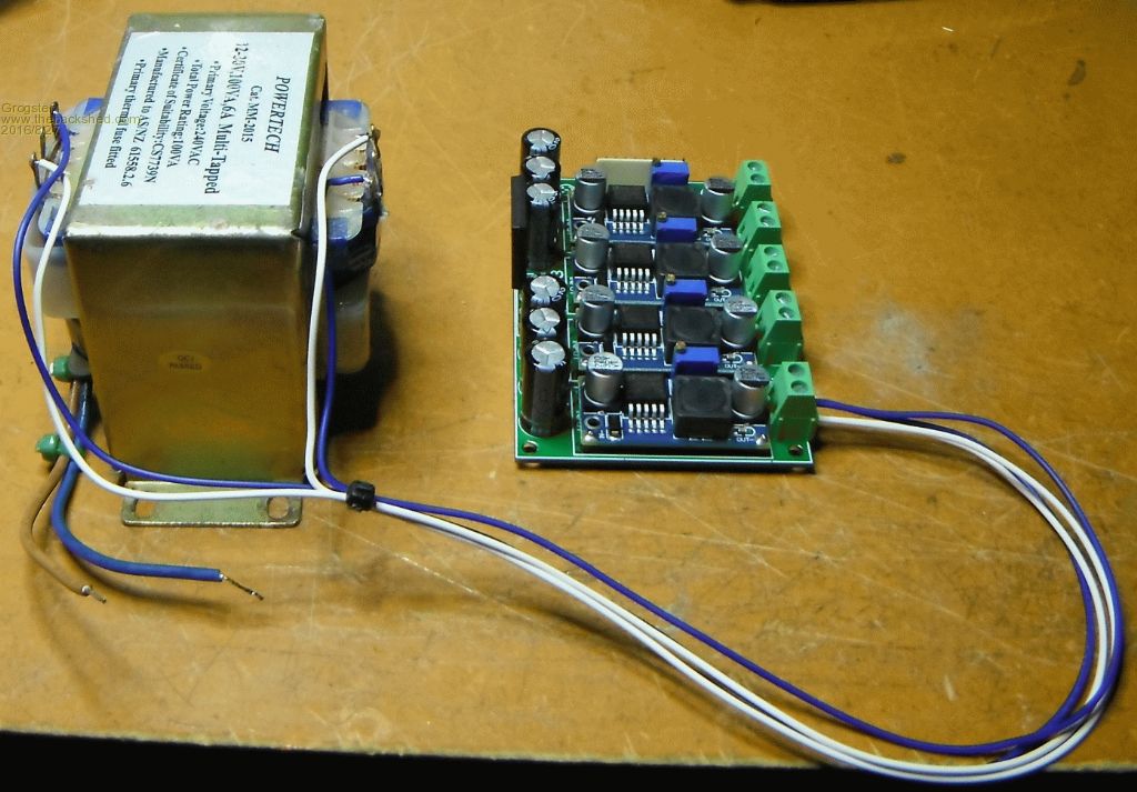
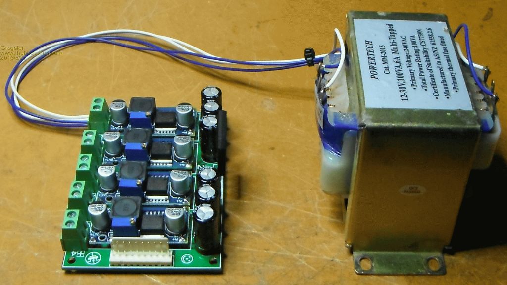
You might not even need the reservoir caps depending on how you use the module and what you are feeding it from, but I like to have them though, as it gives the PSU some headway and stability for different types of loads etc. Tomorrow, I will hook up some dummy loads to the outputs and run some more tests. I need to fix the rectifier bridge to a heatsink before I pull more then an amp or so through it, but that is also on tomorrow's agenda. I would have preferred low-ESR reservoir caps, but they were slightly larger in physical size for the same voltage and capacitance and would not physically fit on the board side-by-side, so I had to stick with bog-standard electro's. Still, this is 6000uF of reservoir, so for all but the thirstiest of loads...... Smoke makes things work. When the smoke gets out, it stops! |
||||
| Zonker Guru Joined: 18/08/2012 Location: United StatesPosts: 772 |
Looks awesome Grogs..! How will you do the first setup..? +5 and +3.3v... Maybe +/-12 for the analog stuff..? Should be a nice bench unit...  |
||||
TassyJim Guru Joined: 07/08/2011 Location: AustraliaPosts: 6538 |
I thought I was smarter. I waited until the RJ45 connectors arrived by slow-boat and then finished creating the part in DEX. It was my best ever board I had milled. And then... First thing I noticed (after milling the board) was the pinout was back-to-front. Second thing I noticed was the RJ45 connectors were straight out from the board instead of at rightangles. I am now waiting for the slow-boat again. A little bit of squeezing is easy in comparison. I also have a few of your modules and they are great for the price. I normally use the fixed voltage ones but having the adjustable ones on hand is nice. Jim VK7JH MMedit |
||||
| Grogster Admin Group Joined: 31/12/2012 Location: New ZealandPosts: 9975 |
Hey folks.
@ Zonker - Setup initially for 3v3, 5v, 9v and 12v in that order 1-4. Transformer is two 12v 3A windings in parallal, although, I doubt I would need 6A of juice, and with that kind of current, I really should be using something with current-limiting, but we will say no more about it.
@ TassyJim - Designing something to fit, then finding the parts don't fit seems to be a case of C'est La Vie I find. Still, it is very annoying when it happens and you are quite sure within yourself that you have it right - only to be proved wrong! Smoke makes things work. When the smoke gets out, it stops! |
||||
| thirsty Newbie Joined: 22/06/2016 Location: AustraliaPosts: 34 |
Grogster, looks like Dex doesn't import gerbers! It appears to handle eagle and dxf, not sure if you can produce those. I was planning on making my own board just for fun though might go to china if this gets too hard 😄 |
||||
| Page 1 of 2 |
|||||
| The Back Shed's forum code is written, and hosted, in Australia. | © JAQ Software 2026 |
