
|
|
Forum Index : Microcontroller and PC projects : E64 Module Footprint needed
| Author | Message | ||||
| skylight Newbie Joined: 10/01/2016 Location: United KingdomPosts: 23 |
I want to make a pcb to accomodate the E64 Module, I have downloaded the constructers pack from Grogsters site and have the gerber file, was wondering if i can import this into AutoDex to give me the footprint? If so could someone be kind enough to give me some pointers on how to do so as im a bit of a novice with AutoDex. |
||||
| Zonker Guru Joined: 18/08/2012 Location: United StatesPosts: 772 |
Hey Ken, Welcome to the forum..! Laying out the E-64 module in Dex is like creating any other part. You know the placement of all the holes for the module, which are on 100 centers, to make the PCB footprint. Then, create a schematic symbol for it that shows the micromite pin numbers for each pin. There are 3 "power" type pins off to one side also... I have Dex and could create a version of this if you wanted, but it might not end up looking like what you want... The best way to learn Dex is to play around with it and see how things work... You could post your version here and see what other Dex users think of it... I am not sure about importing the gerber information from Grogs... It's probably easier to just spin up the part by hand... (just my 2 cents)..  |
||||
Grogster Admin Group Joined: 31/12/2012 Location: New ZealandPosts: 9975 |
Totally agree with Zonker, and that is the way to do it. Note that one of the GIF's in the constructor pack, is a dimensions one for the E64, so that you can do exactly what you are wanting to do - design a footprint for the E64, that you can use in your own PCB designs, and then just plop in the E64 module as the heart of it later. As Zonker says, all pins are on a standard 2.54mm/0.1" grid, so it is really easy to lay down some pads according to the dimensions, and save that as your footprint. You don't need the pads for J1 on your footprint, so then it is just two rows of pads on a standard grid, with three pads to the right of the top row of pads based on the dimensions GIF, which is 7.62mm 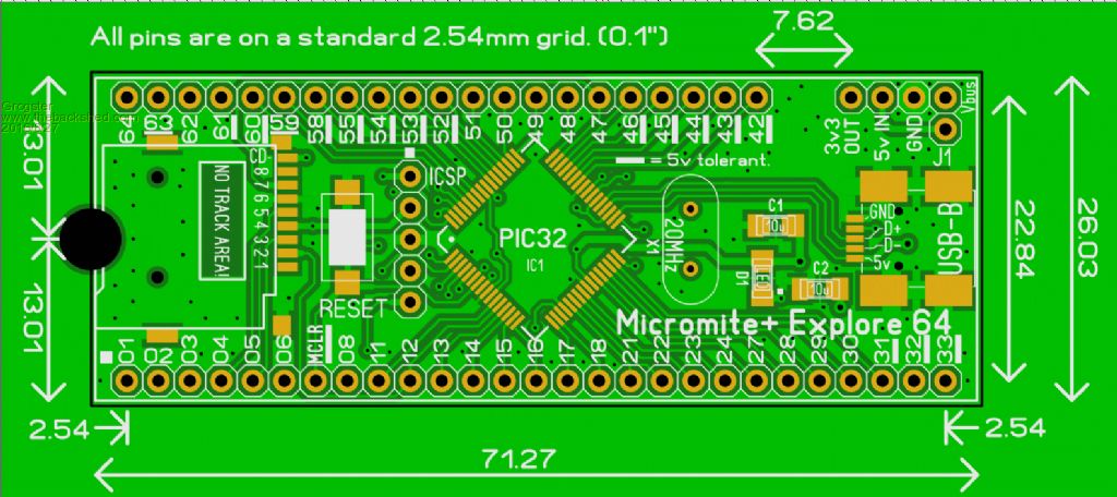
Smoke makes things work. When the smoke gets out, it stops! |
||||
TassyJim Guru Joined: 07/08/2011 Location: AustraliaPosts: 6538 |
This is my feeble attempt. 2016-08-27_074155_Explore64.zip Jim VK7JH MMedit |
||||
| Phil23 Guru Joined: 27/03/2016 Location: AustraliaPosts: 1667 |
Don't have J1 on my E64? Isolates USB power according to the circuit in last months SC? I did wonder how I got rid of USB 5.0V on mine. Phil. |
||||
| Grogster Admin Group Joined: 31/12/2012 Location: New ZealandPosts: 9975 |
Is your E64 a 1B or 1C PCB Phil?(on the back silkscreen, bottom right) Smoke makes things work. When the smoke gets out, it stops! |
||||
| Phil23 Guru Joined: 27/03/2016 Location: AustraliaPosts: 1667 |
Can you do a jpeg or something that us none PCB ones can view Jim. I'm curious. Phil. |
||||
| TassyJim Guru Joined: 07/08/2011 Location: AustraliaPosts: 6538 |
I have updated the DEX part to include pin functions. 2016-08-28_030248_Explore64.zip Phil, I think this is what you are after. 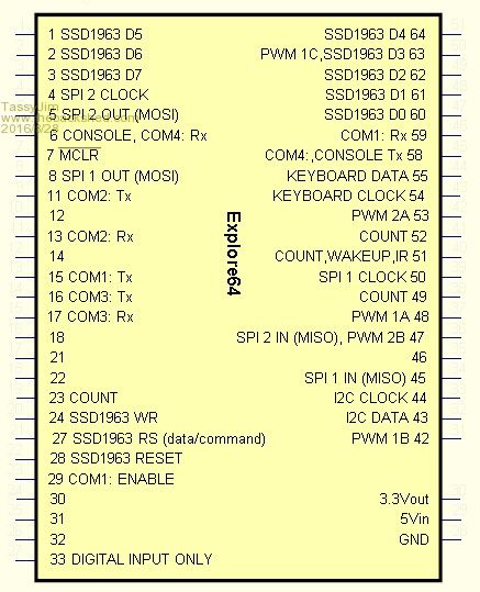
Jim VK7JH MMedit |
||||
| skylight Newbie Joined: 10/01/2016 Location: United KingdomPosts: 23 |
Thanks to all for your help especially TassyJim for his autotrax part, I'm still learning the program and am some way off of making my own parts for it just yet. Btw the PCB I'm hoping to create is a sort of backpack to a 5" TFT so to start will be quite basic with just the connections needed, I may expand later to include extras like RTC, I/O's etc. Once complete ill post it here for comments,advice. |
||||
| The Back Shed's forum code is written, and hosted, in Australia. | © JAQ Software 2026 |
