
|
|
Forum Index : Microcontroller and PC projects : Explore-28 - New MM2 module....
| Author | Message | ||||
Grogster Admin Group Joined: 31/12/2012 Location: New ZealandPosts: 9083 |
Nice one, Rob!  I will have to get my one built now - it's still on the to-do pile...... Smoke makes things work. When the smoke gets out, it stops! |
||||
| WhiteWizzard Guru Joined: 05/04/2013 Location: United KingdomPosts: 2794 |
Neat job there Rob.  Did you hand solder the QFN shown in the bottom picture? WW For everything Micromite visit micromite.org Direct Email: whitewizzard@micromite.o |
||||
| robert.rozee Guru Joined: 31/12/2012 Location: New ZealandPosts: 2294 |
yep, all soldered by hand. the QFN package was 'glued' in place using a tiny drop of nail varnish. next SP-44 rosin based flux was packed around the edges, before soldering using the bit shown in the first photo (by dragging the bit across the pins/pads). the bit is a weller PTK-6 (600 degrees F, 315 degrees C). the rest of the assembly was done with a standard PTA-7 bit (700 degrees F, 370 degrees C). leaded solder was used throughout. the QFN package was actually the easiest part of the assembly, while the USB socket was the most tricky. cheers, rob :-) |
||||
| WhiteWizzard Guru Joined: 05/04/2013 Location: United KingdomPosts: 2794 |
Is that legal these days!  (I use that too - much easier to work with! ) (I use that too - much easier to work with! )For everything Micromite visit micromite.org Direct Email: whitewizzard@micromite.o |
||||
| robert.rozee Guru Joined: 31/12/2012 Location: New ZealandPosts: 2294 |
leaded solder: it is just as legal as lead-acid car batteries  cheers, rob :-) |
||||
| Grogster Admin Group Joined: 31/12/2012 Location: New ZealandPosts: 9083 |
Still legal in New Zealand. Not sure about other areas of the world. I think that leaded solder is illegal in the States, or areas such as California, yes? Smoke makes things work. When the smoke gets out, it stops! |
||||
| lizby Guru Joined: 17/05/2016 Location: United StatesPosts: 3027 |
In the U.S., 60/40 solder is still available to purchase for hobby electronics use (don't know about California). It's prohibited now (so far as I know), for plumbing, and most if not all commercial electronics gear will use lead-free solder. Lead-free does not work well with the cheap Radioshack 15W iron I use (which now appears to have a nearly indestructible tip--2+ years of moderate (and sometimes daily) use with no tip erosion). PicoMite, Armmite F4, SensorKits, MMBasic Hardware, Games, etc. on fruitoftheshed |
||||
| Grogster Admin Group Joined: 31/12/2012 Location: New ZealandPosts: 9083 |
Personally, I don't like lead-free solder. Not for it's merits over leaded, but cos it is a pain in the arse to use - especially with reflow SMD work - due to the extra heat you need to use. I'm also not a fan of it's "Dull" appearance over nice shiny leaded solder, but that is only a personal thing and nothing to do with the solder itself per se'. Glad to hear that lead solder is still available for hobby use in the USA.  I thought that even hobby use of 60/40 was out over there.  Smoke makes things work. When the smoke gets out, it stops! |
||||
| Grogster Admin Group Joined: 31/12/2012 Location: New ZealandPosts: 9083 |
Well, here is my attempt: 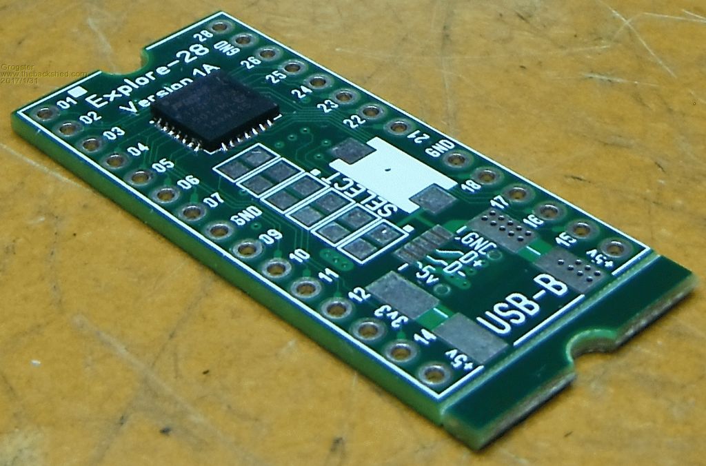 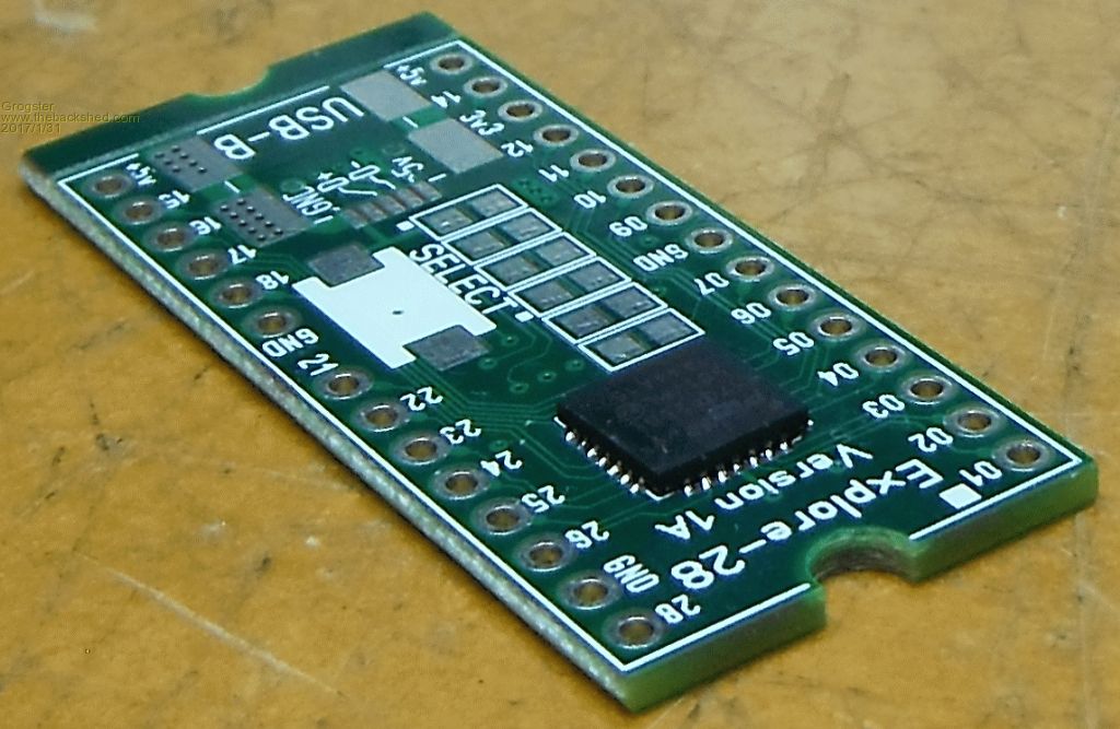 This is the very first QFN I have done, so I will probably get neater as I do more of them. Difficultly level: 5/10. Not really a problem, in other words. This was hand-soldered with a bench iron, same as Rob did his one. In my case, I used a TINY bit of blu-tack under the chip, to both hold it there while soldering, and make it nice and easy to move the chip around for alignment. You press the blu-tack flat with your finger, then press the chip onto that. This means the blu-tack will hold the chip SLIGHTLY proud of the PCB, but that is probably not a bad thing, as the solder can then flow under the pads to form a nice solid connection. The blu-tack holds the chip there while I mount the PCB at 90-degrees so I can see the pads and the lands on the chip. Apply flux-gel, and soldering was easy. Does require about one second longer per "Pin" then the standard QFP chips, but once it is on the move(the solder), then it flows very painlessly to where you expect and want it to sit, so overall, very pleased with how easy they are to solder, when I thought they would be a right pig. I'll try to build the rest of this module tonight depending on time. Rob having got his one finished has prodded me to get a move on! Smoke makes things work. When the smoke gets out, it stops! |
||||
| Zonker Guru Joined: 18/08/2012 Location: United StatesPosts: 761 |
Sweet Grogs..!! I am running out of my "DIP-600-28" boards I made and yours looks awesome..!! These little modules are very useful when working on code to get external hardware drivers working... Just "plug and play"... Nice..! Mine used the FTDI DFN chip for USB and had the RTC/Fram combo on back... I liked the dual Vreg's on it... One for the MM chip, one for the User... Yours uses the newer USB IC..! Nice... Post when you get a batch of them..!! Thanks G..! |
||||
| Grogster Admin Group Joined: 31/12/2012 Location: New ZealandPosts: 9083 |
I hope to finish my module over the weekend. Too many things going on at the moment, and it has been pretty constant since the lightning strike last year. Rob - how are you getting on with your one? Smoke makes things work. When the smoke gets out, it stops! |
||||
| robert.rozee Guru Joined: 31/12/2012 Location: New ZealandPosts: 2294 |
have been tinkering away with it - stress testing to see if i can make it get warm (so far no overheating), checked pin mapping (all correct), and showing it off to a few folks. the only problems i've found so far are a couple of little bugs in the 1455 code, that i have raised with peter: 1. pressing alt-B in teraterm while in programming mode causes the 1455 to release MCLR while not deconfiguring PGC/PGD or exiting programming mode. this can lead to the 1455 and MX170 both trying to drive pins 4 and 5 if a basic program autoruns, however this is an unlikely situation to arise in practice. 2. even when not in programming mode, the 1455 appears to have weak pullups permanently configured on the PGC/PGD pins (4 and 5 again). this may affect use of these pins as analog inputs if not designed around. have yet to look at the 1455 source code to see if this is fixable. oh, and the power LED brightness that i mentioned in email. the form-factor of the device (fitting to a small breadboard) is certainly excellent, robust and very easy to tinker with. having everything including ICSP programmer onboard will be attractive to beginners. now if we could just persuade silicon chip to attach one to the cover of an issue - like what was done with the pi zero in the UK... cheers, rob :-) |
||||
| matherp Guru Joined: 11/12/2012 Location: United KingdomPosts: 8605 |
Rob Haven't received anything from you P |
||||
| JohnS Guru Joined: 18/11/2011 Location: United KingdomPosts: 3678 |
Make them for a retail price of �4 (US $5) or so and maybe they will. John |
||||
| MicroBlocks Guru Joined: 12/05/2012 Location: ThailandPosts: 2209 |
Adding all the parts will make it cost at least 6-7US$ Then add a bit for assembly/handling and 10-15US$ seem to be a cheap price for an assembled version. A kit maybe around 9-12US$. At those prices it is still a work of love as profit is negligible. Microblocks. Build with logic. |
||||
| robert.rozee Guru Joined: 31/12/2012 Location: New ZealandPosts: 2294 |
i'm picking my blasted email system is on the blink again  just received your email, will reply via pm on here. cheers, rob :-) |
||||
| CaptainBoing Guru Joined: 07/09/2016 Location: United KingdomPosts: 1995 |
Nice vid here (about 3mins in) on simple hand soldering QFN https://www.youtube.com/watch?v=F9uNdE_027Q |
||||
| isochronic Guru Joined: 21/01/2012 Location: AustraliaPosts: 689 |
Nice pcb Grogster ... any prices/availability etc yet ? I'll swap some sn-7x if you like .. |
||||
| isochronic Guru Joined: 21/01/2012 Location: AustraliaPosts: 689 |
Well - nice designs - but it looks like there are no gerbers or current availability of either (?)  . .ed - @ Microblocks - is your version available at all ? There is no contact method that works at the moment? |
||||
| Grogster Admin Group Joined: 31/12/2012 Location: New ZealandPosts: 9083 |
Sorry I missed your message above dated 4th - not sure how I did not see that...  We have a working prototype, but nothing available just yet. I am going to put something up on my website in the next few days, and then pre-orders can be accepted. The price will be US$9.99 + P&P for an ASSEMBLED module. No kits will be on offer, as it is not worth the time it takes to assemble kits, when fully assembled modules will be on offer for ten bucks or so. Airmail envelopes will add US$2 to that price for anyone outside of New Zealand, and US$1 for anyone inside of New Zealand.(about $1.40 for NZ Airmail, DLE envelope) You will need to solder on the pin-strips yourself, but they are included. I will post an update here on this thread, when the website has the pre-order thing setup - I hope to do this tomorrow(Sunday 12th). Smoke makes things work. When the smoke gets out, it stops! |
||||
