
|
|
Forum Index : Microcontroller and PC projects : MM DS3231, BMP180 and I2C
| Author | Message | ||||
| Andrew_G Guru Joined: 18/10/2016 Location: AustraliaPosts: 883 |
Hi - this is a follow-up to my earlier post: http://www.thebackshed.com/forum/forum_posts.asp?TID=9090&PN=3 As I get further into the detail I have a few more questions that I'm sure will be trivial to most of you (sorry but I have read all the datasheets to no avail): - I want to sample BMP180 data every 15 minutes and plot it every hour. What are the pros and cons of setting up interrupts (eg as TassieJim does) vs a Do-Loop that tests the times? - am I correct that "RTC GetTime" not only reads the RTC's time but sets the MM's time (and date) to that value? (all this in the background - brilliant!) In I2C communications: - is it OK to connect the SCL and SDA of a BMP180 and a RTC to I2C (17/18) but the Vdd of each to 3.3 and 5V respectively (the latter is so that the RTC's LIR2032 charges) (no smoke so far . . .) - I have a future project where I want to measure two sets of pressures, one at atmospheric and a second at less than this (well within the BMP180's range) - can I address two BMP180's via I2C? (how)? - how does one know that the BMP180 address is &H77? (TassieJim's code to read BMP180 temperature and pressure) - how does one know that the RTC address is &H68? (Geoffg's code for SuperClock) - what does the instruction "I2C Write &H51, 0, 1, 2" do? (It is applied if the RTC is not present in Geoffg's code for SuperClock) Thanks again, Andrew. |
||||
TassyJim Guru Joined: 07/08/2011 Location: AustraliaPosts: 6538 |
The BMP085 has a XCLR pin that can be used a s chip select to allow more than one BMP085 on the bus. The BMP180 doesn't have that option. Read the data sheets. They are readily available and should be studied if you want to get the most out of the devices without too much head-banging. Sometimes, you will need help but when you have the answers and the datasheets to compare them with, you will learn how to decipher the next datasheet. Sometimes (often) when you get a module it has a 3.3V regulator on board allowing 3.3 or 5V supplies to be used. The datasheets will tell you what the chip voltage is likely to be. If your RTC module has a regulator, both devices will be running the I2C at 3.3V The micromite I2C runs at 3.3V although I think all devices are 5V tolerant. The method you use to keep time and program flow will depend on the whole program requirements so there is no best way. Jim VK7JH MMedit |
||||
| Andrew_G Guru Joined: 18/10/2016 Location: AustraliaPosts: 883 |
Thanks Jim. Andrew |
||||
| TassyJim Guru Joined: 07/08/2011 Location: AustraliaPosts: 6538 |
Sorry, I missed that bit. For the BMP180 My version of the data sheet: 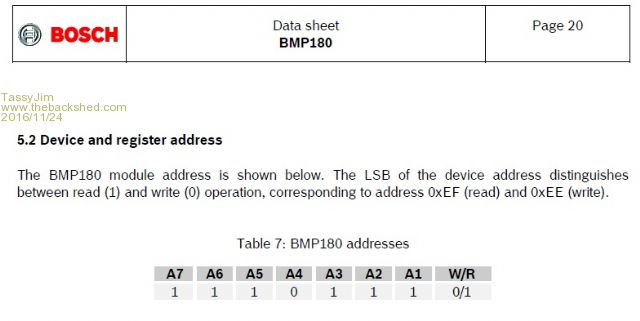 The binary 1110111 is the same as 77 hex The data sheet also talks about EE for write and EF for read. That's just adding a zero or one onto the end of the binary number 11101110 = EE = write 11101111 = EF = read The Micromites add the read or write bit as required so we stick with the 7 bit address. With all I2C addressing, you need to work out if the datasheet is using 8bits (with the direction included) or 7 bits. Fortunately, most data sheets show the address in binary at some stage so it's relatively easy to sort out. If you have Windows10, the calculator in programmers mode is handy for converting to/from binary Jim VK7JH MMedit |
||||
| TassyJim Guru Joined: 07/08/2011 Location: AustraliaPosts: 6538 |
Here's the section of the DS3231 datasheet 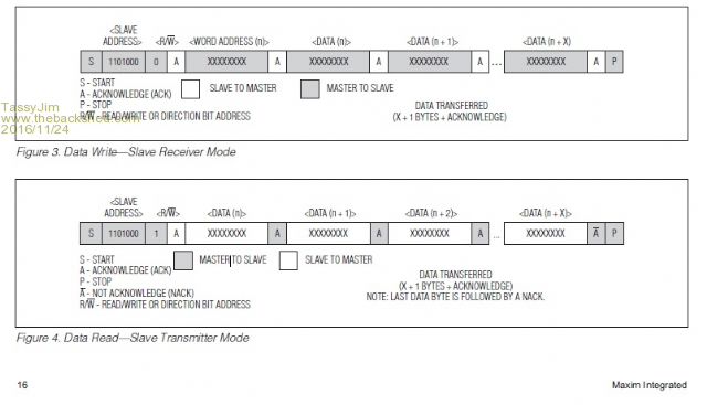 1101000 binary = 68 hex Jim VK7JH MMedit |
||||
| JohnS Guru Joined: 18/11/2011 Location: United KingdomPosts: 4335 |
Sorry, ignore. John |
||||
| Andrew_G Guru Joined: 18/10/2016 Location: AustraliaPosts: 883 |
Jim, Thanks (again). I'd stared at page 20 of the BMP180 datasheet for ages (several times) and not made the link between it being a binary No. that had been converted to hex (I was happy with the hex addresses given on page 21 so had not queried them). Thanks to your explanation I now know to think binary and hex. Cheers, Andrew |
||||
| CaptainBoing Guru Joined: 07/09/2016 Location: United KingdomPosts: 2171 |
Jim is quite right about the datasheets - they will contain all the info you need but it might be a bit cryptic... learning to read them is a bit of a dark art and they all vary in style a bit so you might have to hunt around and "read between the lines". The DS3231 is a good example; nowhere does it say "the device responds to address....." etc. you just have to glean that info when you look at the timing and data format diagrams. Cute. You can always ask here  one thing to remember is that some devices might have address pins on the chip that you have to tie hi/lo in the right pattern (or drive from IO on the pic if that is the flxibility you need - I did this when I needed more 24Cxx EEPROMS on the i2c than I could get with the address bits on offer). These allow you to set the lower 2 or 3 bits (sometime as many as 6!) of the address, so the address specified in the PDF is only a base or starting point - the tiny EEPROM 24Cxx range is a good example here - this is so you can stack several of them on the same bus really easily and have no conflicts when you talk to them. You have your base address plus the binary on the address select pins whch forms the address you use in the i2c routines. It will all "click" into place I promise you. as an aside, this link has the addresses of common i2c chips and is a good start, but not everything is here so you may still end up to your ears in PDFs hth h |
||||
| Andrew_G Guru Joined: 18/10/2016 Location: AustraliaPosts: 883 |
Thanks CaptainB. The link is just the ticket - I'll keep an eye on it as they may update it from time to time . . . Regards, Andrew |
||||
| The Back Shed's forum code is written, and hosted, in Australia. | © JAQ Software 2026 |
