
|
|
Forum Index : Microcontroller and PC projects : Micromite help please
| Author | Message | ||||
| larny Guru Joined: 31/10/2011 Location: AustraliaPosts: 349 |
I want to insert the Micromite programme into a PIC32MX150F128B as shown in the Silicon Chip article May 2014 page 32, Figure 3. I want to use one of the PIC programmers that I already have rather than buy a PICKIT 3. These programmers are designed to programme 12F & 16F PICs which require Vpp = 11 or 13 Volt depending upon the PIC to be programmed. However, the device file PIC32MX150F128B.dev states that the maximum Vpp is 3.6 Volt. I have tried to find the specification for the PIC32MX150F128B but all I could find on the Microchip website was a general specification for the PIC32MX1XX/2XX family. This document does not specify how those PICs are programmed but states that pin 1 is the MCLR pin and also, it is used for reset. I don't see how this pin can be used for both reset and for programming. Any advice will be appreciated. |
||||
| robert.rozee Guru Joined: 31/12/2012 Location: New ZealandPosts: 2528 |
you have several options: 1. pickit 2 (or 3 with alternative firmware) 2. arduino nano, 5 resistors and a 3v3 zener diode 3. pic16F1455 4. an MX170 already loaded with mmbasic pic32prog can use a pickit 2 to program any pic32MX device. the other 3 options require you to assemble a bit of electronics to interfact with the device you want to program. none of the pic32 range of devices can be programmed with older 12F or 16F programmers as the programming architecture is completely different. all the above 4 options make use of a program called pic32prog. pickit 3 uses mplab. cheers, rob :-) |
||||
| larny Guru Joined: 31/10/2011 Location: AustraliaPosts: 349 |
Thanks Rob. But what I'm looking for is an explanation of how the programming is done so I design something to suit. I expect that it will be simple to design something once I know what signals, etc. are required. All the best, Len |
||||
TassyJim Guru Joined: 07/08/2011 Location: AustraliaPosts: 6538 |
Silicon Chip November 2015 "A Cheap Programmer For The PIC32 Microcontroller": by Rob Jim VK7JH MMedit |
||||
| matherp Guru Joined: 11/12/2012 Location: United KingdomPosts: 11512 |
It is done by sending an unlock sequence to the chip and then you have to upload a piece of code (programming executive) and finally you can send the actual program. This is what has been engineered into pic32prog. It is all done at normal 3.3v logic levels on the thee pins MCLR, PGD, PGC but is EXTREMELY complex |
||||
| JohnS Guru Joined: 18/11/2011 Location: United KingdomPosts: 4335 |
We've had rather long thread(s) about it. Look for ICSP or the like. Mchp have a doc about it; I think the current one is this Essentially it's serialised bit-banged (E)JTAG and the MIPS docs are helpful. You can also program from such as RPi, as well as the somewhat weird ones in the long-running thread(s). John |
||||
| larny Guru Joined: 31/10/2011 Location: AustraliaPosts: 349 |
Thanks for the comments. Jim alerted me to the Silicon Chip article, so that is the obvious way to do it. I don't want to re-invent the wheel. I also now understand what Rob meant by option 2 in his post. It is much more complicated than I expected. So I'll build the Silicon Chip version. However, I'll investigate the possibility of using an LED instead of the 3V3 Zener. If it is feasible, it will kill 2 birds with the same brick, i.e. provide a reference of about 3V & act as a "power on" indicator. According to the JayCar catalogue, at 20 mA, the Green LED (ZD-0206) has a voltage of about 3.1V, the Blue (ZD-0215) is 3.5V & the White (ZD-0220) is 3.2V. So I suspect that the Blue one will give about the right voltage at a lower current. Thanks again, Len |
||||
| larny Guru Joined: 31/10/2011 Location: AustraliaPosts: 349 |
I considered 2 options of using an LED in lieu of the 3V3 Zener but both are impractical. 1. In order to do it with a single LED, I would need an LED with a max forward current of at least 60 mA in order to provide a margin for error. I could not find such a LED in either the JayCar or Altronics catalogues. I did not bother to look further. 2. It could be done using two 30 MA LEDs in parallel but this would require a closely matched pair of LEDs so that the current through each was approx equal, i.e. about 25 mA max. So these ideas are not worth further consideration. Thanks again for your help. |
||||
redrok Senior Member Joined: 15/09/2014 Location: United StatesPosts: 209 |
Hi larny;You could use 1 or 2 regular silicon diodes in series with an LED. That way you wouldn't need as much current. Tech note: Low voltage zener's forward voltage varies quite a bit with different forward currents. Generally zeners below about 5.6V act this way. Higher voltages above about 5.6V are considered "Avalanche diodes" and have much sharper voltage vs. current. See:Zener Diodes. Another property of LEDs is they also have "Photo Voltaic" effects. The high current types can generate up to about 10uA of photo current in bright sunlight resulting in an increase in voltage. If you use a zener current of at least 10 times this, say 100uA, this will swamp out the photo voltaic effects. Using an LED + diodes you can kind of program the voltage you need by changing the number of diodes. I would think a blue LED and 1 diode would be about right. Lower voltage, i.e. "redder" LEDs, need more diodes. Have fun!!! redrok |
||||
| robert.rozee Guru Joined: 31/12/2012 Location: New ZealandPosts: 2528 |
because it is a shunt regulator, the load (zener diode, pic32, or some combination thereof) needs to always be drawing 60mA. the only way to decrease this is to increase the values of the three 100 ohm resistors. but if you increase the values of the 100 ohm resistors, then you risk not having enough current to power the pic32 during programming. i chose 60mA as being a safe compromise: microchip suggest the target should draw no more than 25mA, i read somewhere that the pickit2 can supplky at most 50mA, and the usb port is limited to 100mA in total. any zener diode between 2v7 and 3v9 should be fine, or you can use a string of 4 or 5 silicon diodes in series. or, if you must, you can use an 'amplified zener' circuit: 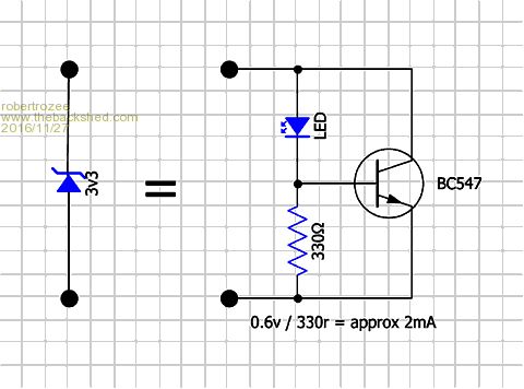 cheers, rob :-) |
||||
| larny Guru Joined: 31/10/2011 Location: AustraliaPosts: 349 |
You could use 1 or 2 regular silicon diodes in series with an LED. That way you wouldn't need as much current. Tech note: Low voltage zener's forward voltage varies quite a bit with different forward currents. Generally zeners below about 5.6V act this way. Higher voltages above about 5.6V are considered "Avalanche diodes" and have much sharper voltage vs. current. See:Zener Diodes. Another property of LEDs is they also have "Photo Voltaic" effects. The high current types can generate up to about 10uA of photo current in bright sunlight resulting in an increase in voltage. If you use a zener current of at least 10 times this, say 100uA, this will swamp out the photo voltaic effects. Using an LED + diodes you can kind of program the voltage you need by changing the number of diodes. I would think a blue LED and 1 diode would be about right. Lower voltage, i.e. "redder" LEDs, need more diodes. Have fun!!! redrok Thanks for the response. I wanted to explore the possibility of using an LED in lieu of the 3V3 Zener so it would both regulate the voltage & give a visual indication. But it is not feasible as I can't find a Blue LED that can handle >50 mA. The issue of the photo current would not be an problem since the current will go into the three 100 Ohm resistors in parallel. So the voltage due to the photo current would be about 10 uA * 33 = 330 uV. So won't do anymore exploration, I'll use a 3V3 Zener. |
||||
| larny Guru Joined: 31/10/2011 Location: AustraliaPosts: 349 |
Thanks Rob. As I just said above, I'll use a 3V3 Zener. I always like to explore other options when I start on a project. All the best, Len |
||||
| robert.rozee Guru Joined: 31/12/2012 Location: New ZealandPosts: 2528 |
btw, a 'construction guide' can be found here: http://www.thebackshed.com/docregister/Browse.asp cheers, rob :-) |
||||
| larny Guru Joined: 31/10/2011 Location: AustraliaPosts: 349 |
Thanks again Rob. I have just printed it. Cheers, Len |
||||
| The Back Shed's forum code is written, and hosted, in Australia. | © JAQ Software 2026 |
