
|
|
Forum Index : Microcontroller and PC projects : Micromite MX270 v5.03.02
| Page 1 of 2 |
|||||
| Author | Message | ||||
kiiid Guru Joined: 11/05/2013 Location: United KingdomPosts: 671 |
With Geoff's approval presenting MMBasic v5.03.02 running on 44-pin MX270 chip with USB. This version is very similar to the MX170 version, but supports direct USB communication and has three serial ports available in Basic, instead of two. I needed it as part of a specific project, but figured it might be useful to many more people as it saves the external USB bridge in small projects, hence the release. 2017-02-17_092839_Micromite-MX270D.X.production.zip In addition to COM1 and COM2, COM4 is also available now like in MM+, and like it again it is shared with the console UART (although available on different pins), so in order to enable COM4 the console should be disabled with OPTION CONSOLE OFF. The USB console is always available, though. The speed is also quite good - 1180 grains at 48MHz with active USB console. In order to make USB functional a crystal is needed, 8MHz in this case. That plus the two pins taken by the USB itself required small reordering of the pinout but it is minimal. Here is the pinout for the 44-pin MX270D chip: (Micromite MX270D) Pinout for 44-pin: 1 : 5V | DIGITAL | COUNT | I2C DATA 2 : 5V | DIGITAL | PWM 2B 3 : 5V | DIGITAL | INT4 4 : 5V | DIGITAL 5 : 5V | DIGITAL 6 : GND 7 : CAP 8 : USB D+ 9 : USB D- 10: Vusb 11: DIGITAL | ANALOG | COM2-RX 12: 5V | DIGITAL | COM2-TX 13: 5V | DIGITAL 14: DIGITAL | ANALOG | SPI CLOCK 15: DIGITAL | ANALOG | PWM 2A 16: GND (AVss) 17: 3.3V (AVdd) 18: RESET 19: DIGITAL | ANALOG 20: DIGITAL | ANALOG | SPI OUT (MOSI) 21: DIGITAL | ANALOG | PWM 1A 22: DIGITAL | ANALOG | PWM 1B 23: DIGITAL | ANALOG | COM4-RX (shared with the console) 24: DIGITAL | ANALOG | COM4-TX (shared with the console) 25: DIGITAL | ANALOG 26: DIGITAL | ANALOG | PWM 1C 27: DIGITAL | ANALOG | COM1-TX 28: 3.3V 29: GND 30: OSC1 8MHz 31: OSC2 8MHz 32: 5V | DIGITAL | COM1-RX 33: CONSOLE Tx (DATA OUT) 34: CONSOLE Rx (DATA IN) 35: 5V | DIGITAL | INT3 36: DIGITAL | ANALOG | INT2 37: 5V | DIGITAL | INT1 38: 5V | DIGITAL | COM1: ENABLE 39: GND 40: 3.3V 41: 5V | DIGITAL | SPI IN (MISO) 42: 5V | Vbus 43: 5V | DIGITAL | COUNT | WAKEUP | IR 44: 5V | DIGITAL | COUNT | I2C CLOCK http://rittle.org -------------- |
||||
| sagt3k Guru Joined: 01/02/2015 Location: ItalyPosts: 313 |
Hey kiiid .... very interesting. A small micromite with usb. I'll try to test it right away. Thanks sagt3k |
||||
| MicroBlocks Guru Joined: 12/05/2012 Location: ThailandPosts: 2209 |
Any change of a version that runs on a 28 pin mx270? Microblocks. Build with logic. |
||||
| kiiid Guru Joined: 11/05/2013 Location: United KingdomPosts: 671 |
Possibly yes, soon. If anyone is trying the current 44-pin version, and come across bugs, please let me know. http://rittle.org -------------- |
||||
| kiiid Guru Joined: 11/05/2013 Location: United KingdomPosts: 671 |
Update to fix a small bug in the handling of pins 19 and 20. 2017-02-18_094936_Micromite-MX270D.X.production.hex.zip http://rittle.org -------------- |
||||
| kiiid Guru Joined: 11/05/2013 Location: United KingdomPosts: 671 |
In case anyone is interested in the MX270 version, releasing here the gerbers for probably the simplest development board for it. I have no plans to manufacture and sell any of these but they can be easily assembled by hand at home. All components are 1206 or similar size for easy manual assembly. PCB size is 77x37.5mm. 2017-02-19_130143_MX2.zip http://rittle.org -------------- |
||||
| jwaldha Newbie Joined: 14/01/2016 Location: HungaryPosts: 10 |
One more vote for 28 pin mx270 ! --- JWaldha |
||||
| kiiid Guru Joined: 11/05/2013 Location: United KingdomPosts: 671 |
I am not planning any work on that at the moment since there is no need for it in my development process, but hopefully Geoff may decide to release a 28-pin version based on the sources of the 44-pin version. Sure there will be room for its application. http://rittle.org -------------- |
||||
| jwaldha Newbie Joined: 14/01/2016 Location: HungaryPosts: 10 |
If I was able to access the source code, maybe I could do the modification. --- JWaldha |
||||
| kiiid Guru Joined: 11/05/2013 Location: United KingdomPosts: 671 |
You will need to discuss that with Geoff. I am ok if he provides the sources for the 44-pin version to you. http://rittle.org -------------- |
||||
| jwaldha Newbie Joined: 14/01/2016 Location: HungaryPosts: 10 |
Here is the hex file for 28 pin version (PIC32MX270F256B). (With Geoff's approval) 2017-04-04_081919_MX270B.X.production.zip For testing I used a CHIPKIT DP32 board. (Ofcourse I replaced the MX250 chip to the MX270.) If you have a hw related question, please refer to the documentation of this board. ChipkitDP32 The original documentation is valid in the following exceptions: The following pins they have lost the original functions: 9, 10 Connect here the 8MHz crystal (and two neccessary capacitors based on the datasheet of the crystal) 23 Connect this pin to the 3V3 (eg. pin13) 15 Connect this pin the 5V comes from USB connector 21 Connect this pin to the D+ signal on the USB connector 22 Connect this pin to the D- signal on the USB connector According the MM+ documentation, the serial console can turn off/on: The current pinmap: 1 - RESET 2 - DIGITAL | ANALOG 3 - SPI OUT | DIGITAL | ANALOG 4 - PWM 1A | DIGITAL | ANALOG 5 - PWM 1B | DIGITAL | ANALOG 6 - PWM 1C | DIGITAL | ANALOG 7 - DIGITAL | ANALOG 8 - GROUND 9 - 8MHz crystal wasted: COM2:TRANSMIT | DIGITAL 10 - 8MHz crystal wasted: COM2: RECEIVE | DIGITAL 11 - CONSOLE Tx (DATA OUT) | COM4 Tx | DIGITAL 12 - CONSOLE Rx (DATA IN) | COM4 Rx | DIGITAL 13 - POWER (+2.3 to +3.6V) 14 - SPI IN | 5V | DIGITAL 15 - VBUS wasted: DIGITAL | 5V | COUNT 16 - DIGITAL | 5V | COUNT | WAKEUP | IR 17 - DIGITAL | 5V | COUNT | I2C CLOCK 18 - DIGITAL | 5V | COUNT | I2C DATA 19 - GROUND 20 - 47uF TANT CAPACITOR (+) 21 - USB D+ wasted: DIGITAL | 5V | COM1: TRANSMIT 22 - USB D- wasted: DIGITAL | 5V | COM1: RECEIVE 23 - VUSB3V3 wasted: ANALOG | DIGITAL 24 - ANALOG | DIGITAL | PWM 2B 25 - ANALOG | DIGITAL | SPI CLOCK 26 - ANALOG | DIGITAL | PWM 2A 27 - ANALOG GROUND 28 - ANALOG POWER (+2.3 to +3.6V) --- JWaldha |
||||
| kiiid Guru Joined: 11/05/2013 Location: United KingdomPosts: 671 |
This is great! I hope a 28-pin USB version might be useful to some people. I believe this is based on the 44-pin version released by me earlier, which means nice working power saving modes for battery operated devices. Only one suggestion - COM2 is software UART, so it is probably worth moving it over to another pair of pins to increase the overall functionality. I would suggest pins 6 and 7 (sacrificing PWM1C when COM2 is used) http://rittle.org -------------- |
||||
jman Guru Joined: 12/06/2011 Location: New ZealandPosts: 711 |
Hi Thanks for this kiiid and jwaldha (for the 28 pin version) Time to spin up a 28pin version. This will be great for projects where the pin usage is not a concern. Regards Jman |
||||
| Zonker Guru Joined: 18/08/2012 Location: United StatesPosts: 761 |
Wow..!! Thanks, Gents... This 28 pinner (and 44) USB firmware is a good addition (imho) All the source code gurus deserve a big "tip of the hat"  |
||||
| jwaldha Newbie Joined: 14/01/2016 Location: HungaryPosts: 10 |
Here is the solution. 2017-04-05_170013_MX270B.X.production.zip I corrected the pin allocation for COM2. (COM2_TX: pin6, COM2_RX: pin7) A little bonus: You can freely select pins for COM2! To do all that is required to create two integer variables: COM2_RX_PIN and COM2_TX_PIN. If these variables are exist and contains valid (and free) pin numbers when execute the [OPEN "COM2:xxx"] command then this pins will be used. If these variables are exist, but not contains valid (and free) pin numbers, then You get an error message. If these variables are not exist, then the new defaults (6,7) will be used. These pins will be exclusively allocated for COM2 until you close the COM2. The allocated pins will be released again after You close the COM2. --- JWaldha |
||||
| isochronic Guru Joined: 21/01/2012 Location: AustraliaPosts: 689 |
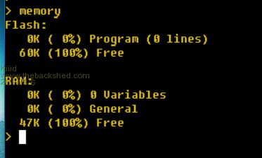
Is the memory available decreased (ie because of the usb stack) ? |
||||
| kiiid Guru Joined: 11/05/2013 Location: United KingdomPosts: 671 |
 http://rittle.org -------------- |
||||
| sagt3k Guru Joined: 01/02/2015 Location: ItalyPosts: 313 |
Hi jwaldha Concerning 28pin version PIC32MX270F256B, Could you make a quick summary of pin used definitively? Thanks sagt3k |
||||
| jwaldha Newbie Joined: 14/01/2016 Location: HungaryPosts: 10 |
Hi, Antonio The current default pinmap of MX270USB: 1 - RESET 2 - DIGITAL | ANALOG 3 - SPI OUT | DIGITAL | ANALOG 4 - PWM 1A | DIGITAL | ANALOG 5 - PWM 1B | DIGITAL | ANALOG 6 - PWM 1C | DIGITAL | ANALOG | COM2 Tx 7 - DIGITAL | ANALOG | COM2 Rx 8 - GROUND 9 - 8MHz crystal 10 - 8MHz crystal 11 - CONSOLE Tx (DATA OUT) | COM4 Tx | DIGITAL 12 - CONSOLE Rx (DATA IN) | COM4 Rx | DIGITAL 13 - POWER (+2.3 to +3.6V) 14 - SPI IN | 5V | DIGITAL 15 - VBUS 16 - DIGITAL | 5V | COUNT | WAKEUP | IR 17 - DIGITAL | 5V | COUNT | I2C CLOCK 18 - DIGITAL | 5V | COUNT | I2C DATA 19 - GROUND 20 - 47uF TANT CAPACITOR (+) 21 - USB D+ 22 - USB D- 23 - VUSB3V3 24 - ANALOG | DIGITAL | PWM 2B 25 - ANALOG | DIGITAL | SPI CLOCK 26 - ANALOG | DIGITAL | PWM 2A 27 - ANALOG GROUND 28 - ANALOG POWER (+2.3 to +3.6V) Since the COM2 is implemented in software, it is make to possible to use any free I/O pin for COM2 Rx and Tx functionality. This solution is use these technique: To do all that is required to create two integer variables: COM2_RX_PIN and COM2_TX_PIN. If these variables are exist and contains valid (and free) pin numbers when execute the [OPEN "COM2:xxx"] command then this pins will be used. If these variables are exist, but not contains valid (and free) pin numbers, then You get an error message. If these variables are not exist, then the new defaults (6,7) will be used. These pins will be exclusively allocated for COM2 until you close the COM2. The allocated pins will be released again after You close the COM2. Some examples: The serial data received on pin 24 and serial data transmitted on pin 25. Pins 24, 25 are free: > list Dim COM2_RX_PIN As integer Dim COM2_TX_PIN As integer COM2_RX_PIN = 24 COM2_TX_PIN = 25 Open "COM2:4800" As #2 Close #2 > > run > Pin 24 is not free, beacuse allocated for DigitalOutput: > list Dim COM2_RX_PIN As integer Dim COM2_TX_PIN As integer COM2_RX_PIN = 24 COM2_TX_PIN = 25 SetPin 24, dout Open "COM2:4800" As #2 Close #2 > run [6] Open "COM2:4800" As #2 Error: Pin 24 is in use > Same as above, but pin 24 is released with "SetPin 24, off" command: > list Dim COM2_RX_PIN As integer Dim COM2_TX_PIN As integer COM2_RX_PIN = 24 COM2_TX_PIN = 25 SetPin 24, dout SetPin 24, off Open "COM2:4800" As #2 Close #2 > run > [/code] Pin 24 is not free, beacuse allocated by "PWM 2, 1000, 10, 10" command: > list Dim COM2_RX_PIN As integer Dim COM2_TX_PIN As integer COM2_RX_PIN = 24 COM2_TX_PIN = 25 PWM 2, 1000, 10, 10 Open "COM2:4800" As #2 Close #2 > run [6] Open "COM2:4800" As #2 Error: Pin 24 is in use > Same as above, but pin 24 is released with "PWM 2, stop" command: > list Dim COM2_RX_PIN As integer Dim COM2_TX_PIN As integer COM2_RX_PIN = 24 COM2_TX_PIN = 25 PWM 2, 1000, 10, 10 PWM 2, stop Open "COM2:4800" As #2 Close #2 > > > run > Pin 24 is allocated for COM2 Rx. > list Dim COM2_RX_PIN As integer Dim COM2_TX_PIN As integer COM2_RX_PIN = 24 COM2_TX_PIN = 25 Open "COM2:4800" As #2 SetPin 24, dout Close #2 > run [6] SetPin 24, dout Error: Pin 24 is in use Same as above, but pin 24 is released with "Close #2" command: > list Dim COM2_RX_PIN As integer Dim COM2_TX_PIN As integer COM2_RX_PIN = 24 COM2_TX_PIN = 25 Open "COM2:4800" As #2 Close #2 SetPin 24, dout > run > I hope I could help you! Regards, Janos --- JWaldha |
||||
| sagt3k Guru Joined: 01/02/2015 Location: ItalyPosts: 313 |
Hi Janos Thanks ...  Excellent, exactly what I had asked and above all with the examples. Excellent, exactly what I had asked and above all with the examples.Some questions: 1) Given the features of moving the COM2 on others pins (COM2 sw), Can We also have the firmware for the 44pin? 2) Do you think keep this code aligned with Geoff's features in future ? Obviously with the approval of Geoff and guru of project. Thanks sagt3k |
||||
| Page 1 of 2 |
|||||
