
|
|
Forum Index : Electronics : Warpspeed’s MOSFET mounting method
| Author | Message | ||||
| Warpspeed Guru Joined: 09/08/2007 Location: AustraliaPosts: 4406 |
I actually meant what does the waveform on the dc supply look like. This definitely needs a stiff low impedance dc supply, and some very large electrolytics, should help a lot. The problem is that the voltages created by each inverter sometimes add together, and sometimes subtract from each other in order to generate all the very fine steps. When subtracting, power flows the reverse way from the load back to the dc source. There is a HUGE amount of circulating energy, and if you have a weak and wobbly dc source, the dc supply voltage is going to look like a mess, and so will your output waveform. Look at the dc supply waveform, and try to make that as clean as possible. Cheers, ĀTony. |
||||
renewableMark Guru Joined: 09/12/2017 Location: AustraliaPosts: 1678 |
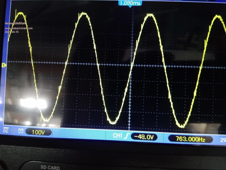 This is what mine looks like with a weak DC supply. That's not your problem, something is busted big time. Cheers Caveman Mark Off grid eastern Melb |
||||
| renewableMark Guru Joined: 09/12/2017 Location: AustraliaPosts: 1678 |
Hook up one torroid at a time and post the pics of each 4 on their own. Cheers Caveman Mark Off grid eastern Melb |
||||
| wiseguy Guru Joined: 21/06/2018 Location: AustraliaPosts: 990 |
You're definitely getting a good handle on this stuff Mark.... starting to sound like an electronics engineer  Your helpful hints to others are usually spot on - well done I am impressed. Hope this does not come across as patronising but credit where credits due. If at first you dont succeed, I suggest you avoid sky diving.... Cheers Mike |
||||
| Warpspeed Guru Joined: 09/08/2007 Location: AustraliaPosts: 4406 |
Kanchana is running straight off a fairly light duty switching power supply, which is going to have far worse dynamic characteristics than Mark's resistor. You cannot throw big chunks of pulsing power back INTO a switching regulator and expect it not to become very unhappy. At least a resistor works in both directions. If you can hook up your oscilloscope to the dc supply, I think that is going to look surprisingly awful. It really needs a big old battery, or at least a few hundred thousand microfarads to calm down the dc. Cheers, ĀTony. |
||||
| Volhout Guru Joined: 05/03/2018 Location: NetherlandsPosts: 3476 |
@Warpspeed, I looked at your inverter design, and noticed a lot of isolated switchmode power supplies (two at each gate driver). Have you ever checked this method (see attached). It can be used for low frequencies also, you basically charge (and discharge) the gate capacitance of a FET or IGBT.... Found this interesting (although a completely different application). Using your controllerboard, you would only need a different EPROM content, a strong ON and OFF pulse, and some maintenance pulses in between. @kanchana: you could have the secondary side of one of the smaller transformers swapped (inverting the contribution of one of the drivers). Volhout energies-12-02406.zip Edited 2020-04-15 23:41 by Volhout PicomiteVGA PETSCII ROBOTS |
||||
| kanchana Regular Member Joined: 08/05/2018 Location: Sri LankaPosts: 56 |
Again I found there was power negative disconnected from one module , connected it got a nice sine wave . 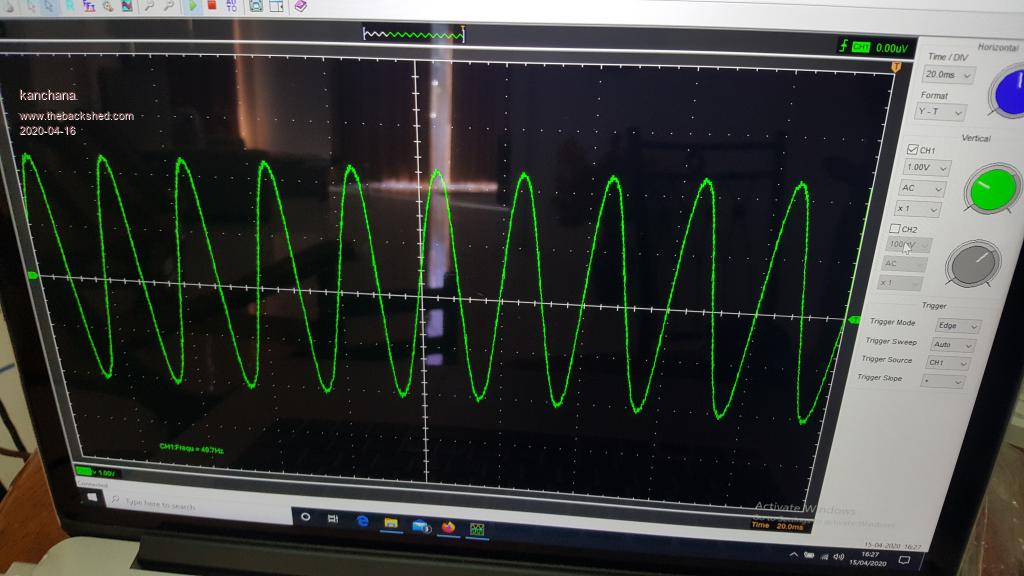 But now when i tried to connect some electrolytes and power with PSU , it pulses on and off trying to startup . probably 5A current from PSU is not enough to start up. Tomorrow will connect it to a large battery bank . hopefully noting will blow up Regards kanchana |
||||
| Warpspeed Guru Joined: 09/08/2007 Location: AustraliaPosts: 4406 |
That is a very nice sine wave Kanchana, well done  Once you have a rock solid dc supply that is not jumping around, all the crap just vanishes. Cheers, ĀTony. |
||||
| Warpspeed Guru Joined: 09/08/2007 Location: AustraliaPosts: 4406 |
Yes indeed, there are sixteen isolated dc supplies required to dive sixteen isolated gate driver circuits which presents a bit of a problem. The small Chinese direct off line switching power supplies that I used are very readily available for around two dollars each, and only draw about 250mW each. Its a very low cost practical solution for a public domain type of do it yourself project. These little supplies are very tough, voltage regulated and short circuit protected, and I have yet to blow one up. There are quite a few other alternatives of course, but nothing quite as cheap and easy to use and get going. I have been building Warpverters of different types for over thirty years, and each new design has been simpler using fewer parts as the ideas and improvements very slowly came to me one by one over that time frame. It will never be viable as a commercial product because of the high cost of the transformers. But at power levels above about 5Kw, it has definite advantages for home construction, because its all so much less critical of physical layout than high frequency pwm. Cheers, ĀTony. |
||||
| kanchana Regular Member Joined: 08/05/2018 Location: Sri LankaPosts: 56 |
Thank you tony . I tried with a larger battery bank and the start up is eratic same as before with caps Tthose smaller power supply units pulses , after several times manage to start once , next time 2 diagonal mosfets in the largest tranformer blows . Battery volatge is 55.4 volats my be it is too low to start up those smaller psu units ? . Will try charging the battey . it is possible to charge the caps initially then connect the power to the controller board via a switch ? Regards kanchana |
||||
| Warpspeed Guru Joined: 09/08/2007 Location: AustraliaPosts: 4406 |
That might be a good idea, I know Klaus originally had some problems with starting up as well. What Klaus did was run a separate independent boost type inverter to generate +60v dc regulated from his 48v battery. Then drive all those little isolated supplies from that +60v. This was either the supply, or something very much like it: https://www.ebay.com.au/itm/DC-DC-Inverter-8-5V-50V-To-10V-60V-Modules-Power-Supply-Boost-Module-Converter/183996201368?hash=item2ad7073998:g:qXgAAOSw4TVdpcoX When that was all up and running, he then charged up his main dc supply rail and electrolytics through a current limiting resistor. That causes the output sine wave to gradually build up from nothing. After several seconds, then close the main dc input circuit breaker to the inverter. My own Warpverter runs at 100 volts dc, so I have no problems with those little supplies starting up reliably as the main system voltage builds up through a current limiting resistor from 0 to 100v. However you finally decide to do it, the dc input voltage sensing for the control board will need to come direct from the main dc battery supply, but the control board power could come from somewhere else. Some of those little supplies start up at around 35 volts, others may need 45 volts which is getting dangerously high for a less than fully charged 48v battery. Klaus's e-bay boost inverter will start up from as little as 12v !! and still deliver +60v output for any input between 12v and 60v. That is pretty fool proof. Edited 2020-04-16 15:50 by Warpspeed Cheers, ĀTony. |
||||
| Murphy's friend Guru Joined: 04/10/2019 Location: AustraliaPosts: 580 |
Hi Kanchana, I have permission from 'klaus' to help you with the inverter startup troubles. Wire the power to it as per attached schematic and follow instructions on it. You do *not* need a boosted driver supply if you do that. 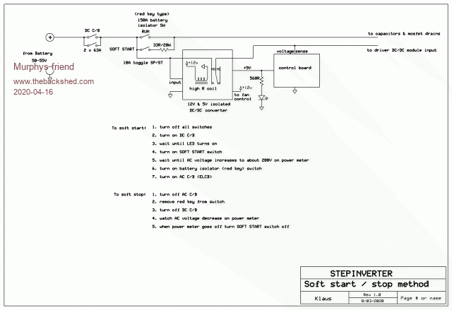 Good luck  |
||||
| Murphy's friend Guru Joined: 04/10/2019 Location: AustraliaPosts: 580 |
Further to the above schematic, the little 5V DC/DC converter on warps board has been removed and the 5V supply to the board are as shown above. |
||||
| kanchana Regular Member Joined: 08/05/2018 Location: Sri LankaPosts: 56 |
Thanks Murphy's friend, So I need 2 DC to Dc converters 12v and 5v 12v to drive the relay and fans and 5v to supply the controller board Regards kanchana |
||||
| Murphy's friend Guru Joined: 04/10/2019 Location: AustraliaPosts: 580 |
What klaus uses is one 50+V to 12V *isolated* DC/DC converter(~2A), supplying 12V for the fans and 12V power to another little buck converter (can be non isolated, about 30v input, output adjustable to 5V ebay special). This then provides the 5V for the control board hence the DC/DC on that board is not required. Note, doing that separates the battery voltage sensing from the control boards 5V rail. Patience is required after following the slow start instructions, it can take 10 seconds for the LED to light and a further 10 or more seconds for the AC to rise to the required voltage level. This slow starting ensures even a small power supply can start & run this inverter which has an idle current of less than 0.5A from the supply set at 55VDC. Any AC load depends, of course, on what that power supply can offer. |
||||
| Warpspeed Guru Joined: 09/08/2007 Location: AustraliaPosts: 4406 |
Excellent !! I know Klaus had a few difficulties with starting up initially, and tried several different schemes before finally ending up with something he was completely happy with. Thank you Murphy's Friend for clarifying the details. Cheers, ĀTony. |
||||
| renewableMark Guru Joined: 09/12/2017 Location: AustraliaPosts: 1678 |
Ahhhhhh..... now it makes sense. Cheers Caveman Mark Off grid eastern Melb |
||||
| kanchana Regular Member Joined: 08/05/2018 Location: Sri LankaPosts: 56 |
Thanks guys for the explanation .Will update the progress Regards kanchana |
||||
| Murphy's friend Guru Joined: 04/10/2019 Location: AustraliaPosts: 580 |
a few more observations for kanchana. The 5VDC could be also from an ordinary 5V regulator, it most likely would not even need a heat sink since the control board electronics consume so little power. Klaus says he used what was on hand. The important bit is the relay, it ensures that all 16 little DC/DC driver supplies start up at once from the 50+ battery voltage. If they were to be powered from the capacitor rail they would randomly start up as the capacitor voltage rises on start up. Since that relay is on during the whole time the inverter is running one with very low coil power (high resistance) is a good idea. Since the 12V relay is powered from the isolated DC/DC module it only closes after the 5V to the control board are established and that board is up and running. So, when the relay closes all the drivers are going with the correct wave forms present at the mosfet gates. But nothing happens at the transformers yet as the large capacitors have no charge yet. Initiating their charging by the 'slow start' switch ramps up the AC slowly at the capacitor charging rate, very nice to observe that on the oscilloscope. It is therefore *very* important that there is *no* remaining charge in the big caps for a smooth soft start. If the inverter is shut down exactly as noted on the schematic above the capacitors are discharged by the inverter's electronics. Again, very interesting to observe this on a CRO, the AC wave form is stable and clean to well below 10VDC at the caps. Lastly, the 'red' battery isolator switch was chosen because it can handle 150Amps when closed and it was cheap. BUT, it is only rated for 24VDC or so and switching any power at 50VDC would most likely weld the contacts together. So, it is *very* important that this switch only switches the <0.5 Amps power for the electronics when it it opens or closes - all the AC load MUST be off to ensure that. Never use that switch to turn off the inverter under load, that is what the DC & AC circuit breakers are there for. |
||||
| Warpspeed Guru Joined: 09/08/2007 Location: AustraliaPosts: 4406 |
All these details are important, and need to be very carefully thought through. Its not difficult, and any issues that arise can be readily overcome. The main thing is the inverter is now working, and it just needs some monitoring, protection, and a safe and gentle means of starting up and shutting down. Cheers, ĀTony. |
||||
