
|
|
Forum Index : Electronics : Various aspects of home brew inverters
| Author | Message | ||||
| Warpspeed Guru Joined: 09/08/2007 Location: AustraliaPosts: 4406 |
It looks like your 50uH series choke resonates about 80Khz when connected to the capacitive primary winding, which is excellent. At 20 Khz, the input side of the choke will look like a very efficient inductor (as it should). But the main transformer itself resonates at only around 4Khz, so without the series choke fitted, the input impedance across the primary is going to be predominantly capacitive, and extremely low at 20 Khz. That primary leakage inductance of 10uH is very good too, as its less than a thousandth of the unloaded 10.6mH primary inductance. Try measuring the secondary inductance directly (at 100 Hz) and then try shunting it with additional capacitance to bring the resonance point down from 4Khz to about roughly 75 Hz. That should further increase the 20Khz attenuation and improve the waveform at 50 Hz. Cheers, �Tony. |
||||
| dom2402 Newbie Joined: 22/05/2012 Location: AustraliaPosts: 3 |
does any one know if this fet is suitable to use in this inverter it is rated at 100v 450w total disipation 560amp pulsed STY140NS10 I know there are no fakes as it is hard to find even on aliexpress there are only 3 listings. 2017-04-26_035658_en.CD00002559.pdf |
||||
| poida Guru Joined: 02/02/2017 Location: AustraliaPosts: 1432 |
HI Dom I would be the last to ask any design questions but I'll answer first. The FET is 100% avalanche rated - good 100V Vds - good Rds-on at 9mOhm - good I have no idea if total gate charge is too much for your design you have in mind. We here tend to try things and if afterwards we don't have to spend the next 1/2 hr picking bits of broken FETs off the floor we conclude the test a success. I like the large TO-247 package too. wronger than a phone book full of wrong phone numbers |
||||
| dom2402 Newbie Joined: 22/05/2012 Location: AustraliaPosts: 3 |
thanks poida I know the chines sell it as a cheap alternative to some other fet but seams a very robust fet 450w dissipation i have a few of them right now the only draw back is the mounting method, they have no hole to be mounted with you have to use some kind of bar across them. |
||||
Madness Guru Joined: 08/10/2011 Location: AustraliaPosts: 2498 |
I have had perfect results with HY4008W FETs from this supplier on Aliexpress the link is for a 100 lot which works out to $1.47 AUD each, but they sell smaller lots also. The ones I got from them have lower RDS on than what the specs should be (which is good). Oztules is now using 4 of these per leg and can still get 20KW startup power. You can spend a lot of time and money trying different things, it is much easier to follow what others have found works. There are only 10 types of people in the world: those who understand binary, and those who don't. |
||||
| poida Guru Joined: 02/02/2017 Location: AustraliaPosts: 1432 |
Part 7 Primary current waveforms with different inductors plus efficiency calculations It is time to look at this inverter prototype under significant loads. My test gear can provide a DC supply up to 10 Amps only. So this means I have to use the 2 x 100A 12 Fiamm batteries to supply the required grunt. Under load they run at about 25V so I removed turns from the primary (was 25 T at 0.7Vrms/turn) to now 19T. Test conditions now are: AC load 480Wrms and it�s a quartz halogen light so the power factor = 1.0 AC output 230Vrms DC supply around 25.5V I test 3 inductors. 2 turns in the ferrite E core (50uH) 7 turns in the laminated steel toroid (16uH) 13 turns in laminated steel toroid (50uh) Yellow trace is DC bus current, 6.1 Amp/div. Blue is AC output Pink is primary winding current, 24.4 Amp/div. The oscilloscope calculates the RMS voltage of this which I use later. first is the E core at 50uH at idle 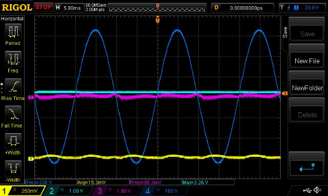 then under 480W load. Notice the large primary current swings from PWM. This is still eliminated at the secondary winding though. 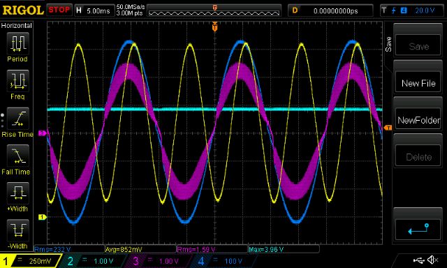 next is the 16uH steel toroid at idle. MORE PWM current swings than the 50uH E core 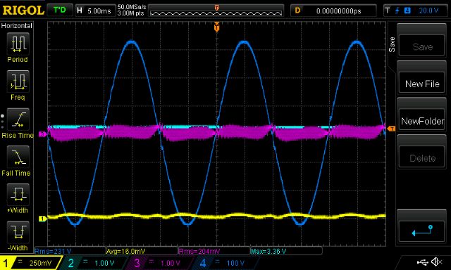 then under the same load. LESS PWM current swings than the 50uH E core.  hmm. last is the 50uH steel toroid at idle. same low PWM current swings as the 50uH E core 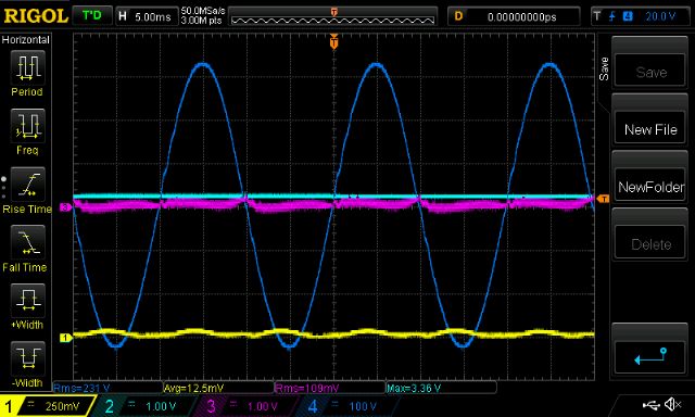 and under load, we get the lowest PWM current swings of all. 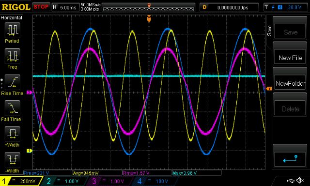 Now I want to show the efficiency of this setup. I measured the primary winding resistance at 15.4 mOhm, and secondary at 45 mOhm The primary is wound with 2 x 6mm2 copper. This is nowhere large enough for a real inverter. The inductor is wound with a single 6mm2 copper wire. I measured the inductor plus current sensor at 5.4mOhm (easy to measure these, just put a fixed current into the winding and get the millivolts, R = V/I. done) We have the primary winding current as calculated by the DSO. Test conditions: AC Voltage 219Vrms (measured by a Power Mate Lite wattmeter. very good specs as a matter of fact) AC power 434Wrms Primary current 37.1Arms DC Bus current 19.4A DC supply 25.3V Power in = 25.3 x 19.4 = 491 W loss = 57 W efficiency = 434/491 = 88.4 % This is not so good. Let�s see where some losses may reside. Secondary winding sees 434/219 = 1.98 Amps and I2R loss = 1.98 x 1.98 x 45mOhms = 0.18W Primary winding I2R loss = 37.1 x 37.1 x 15.4e-3 = 21.2 W Inductor copper loss = 7.4W So the primary winding circuit accounts for over 1/2 of the loss The mosfets are IRF3808. I have 3 per H bridge leg so there are 2 x (3 in parallel) also in the primary circuit. Rds(on) is 7mOhm. I figure series resistance is 4.6 mOhm So maybe the loss when the fets are ON is 6.3 W So far there is 6.3 + 7.4 + 21.2 + 0.18 = 35W loss in the primary circuit. If I use 4 x the copper area (50mm2) then the losses will drop by 3/4 of the 28W primary winding+inductor Then I should get a loss of 36W total at 434W output which is 92.3% efficiency. Now this is looking like a real inverter. When running these tests the H bridge remains at ambient temperature with no fans. My calibrated finger can�t feel any extra warmth from the 20 second test runs at load. wronger than a phone book full of wrong phone numbers |
||||
| Warpspeed Guru Joined: 09/08/2007 Location: AustraliaPosts: 4406 |
There will also be a constant added loss due to magnetizing and eddy current losses in the transformer toroidal core. That could be quite substantial, probably accounting for most of the missing 22 watts of loss. That should also show up as as parasitic idling power under no load. The peak to peak PWM current will always be inversely proportional to the inductance of the primary choke, but this inductance is not going to stay constant. The ferrite will very quickly saturate at only a very few amps. It should work well to reduce mosfet switching losses under no load idling conditions, but will do nothing at all to reduce the PWM current peaks at full output power. A tape wound toroidal choke will take about four times the magnetic flux as ferrite before it saturates, and as it probably also has a much larger cross sectional area than the ferrite E cores, it adds even more to that. But it too will eventually saturate. The way to do this is to use a laminated steel core, but with a large air gap. A grid tie choke will give us exactly that, a pair of C cores with an introduced air gap between the two halves. But do not expect a choke out of a 1.5 Kw grid tie to work in an 8Kw inverter at full flat out power. We are going to either have to string several re wound grid tie chokes together, or go to something similar but larger. There is also no reason why we cannot use both a small ferrite choke in series with a much larger steel cored choke, although if the steel choke is well up to the job, it will probably be found to be all you need. Conclusion. Adding a choke to the primary is a very good way to reduce peak PWM current which will both reduce mosfet switching losses and improve reliability by reducing the stresses on the mosfets. Any choke will eventually saturate if the ampere turns are too high for it. More turns creates more inductance, but lowers the saturation threshold. Once it has saturated, the inductance effectively falls to near zero. Definitely not what you want to happen at peak output power. There will be an optimum number of turns which gives the highest inductance, where it still has some safe margin below final saturation. Cheers, �Tony. |
||||
| poida Guru Joined: 02/02/2017 Location: AustraliaPosts: 1432 |
Warpspeed: I like how the testing of the 3 inductors shows how things change as power is increased. When measuring their inductance, we test with a tiny current from the LCR meter. We need to test under realistic conditions to prevent saturation in the designs. I plan to change the toroid over to the 3kW one and test at about 1500W to see how the last 50uH steel core choke goes than. I find this result applicable to Tinker and Madness's problems with damaged fets. They had issues when using the E core chokes and we all were wondering why. Gate drive was proven to be good. I now think the E core choke is likely the source of the problem. I measured idle current with the above setup and it is about 0.27A at 27.3V DC This is about 7.5W and I wonder if it is constant over all loads. I need to read more on eddy current (and other) losses in the toroid. Now I see the need for large area primary windings, the question is where to get it. I don't want to just spend $$ on something from Jaycar or Middys. Using many strands of enameled copper inside plastic tubing seems possible. There is a 3hp 3 phase motor going to scrap at work. Maybe some wire in there... What's the best and zero cost source for the primary winding? wronger than a phone book full of wrong phone numbers |
||||
| Warpspeed Guru Joined: 09/08/2007 Location: AustraliaPosts: 4406 |
Big fat primary is always going to be better. The more copper you can stuff through the hole the higher the power rating, and the greater the efficiency. Its a win win. Skinny wire is fine for a first initial test to determine a suitable number of turns to get the output voltage into the desired range. Nothing wrong with joining up a few odd lengths of wire for testing. Big round wire like welding cable or battery jumper leads are a simple answer, but it does leave a lot of large unusable voids between the turns. Multiple skinny wires in parallel are always going to be the best way to get the maximum amount of copper into the available space. Zero cost means recycling something, so whatever you can beg, borrow, or steal will be it. You could try your local friendly smiling scrap metal merchant, he probably has bins piled high with copper wire out the back, which he will be quite happy to overcharge you for. But its still going to be cheaper than buying new. About salvaged grid tie chokes. A while back I tested one of these, and it had two windings each of 42 turns, and it saturated just above thirty amps. I cannot now remember the exact figure, but can always do a retest. Anyhow, that is 84 turns x 30 amps or 2,520 ampere turns. That will be a constant for that particular core with the particular air gap that it has. So its pretty easy to work out where a particular number of turns on that specific core are going to saturate, without actually testing it. For example, ten turns would saturate at 252 amps if those original figures are correct. Again, inductance is proportional to turns squared. So if we know that 84 turns gives us (maybe ?) 3,000 microhenries, we can work out the inductance for one single turn. One turn would be 3,000 divided by 84 times 84 = 3000/7056 = 0.425 microhenries per turn. With that figure, and knowing that inductance equals turns squared, ten turns would be 0.425 microhenries x 10 x 10 = 42.5 microhenries. So its possible to rewind one of these grid tie chokes with far fewer turns, and make what used to run at a few hundred volts work at a few tens of volts at similar power levels. This is all a pretty safe assumption. But if you need more, you could run more than one choke. Either two dual winding chokes in series, or one individual choke on each side. It a case of playing with the numbers, working out how many turns can fit onto the core, and by trial and error coming up with something practical that has enough inductance and a suitably high saturation threshold to safely do the job. I have a deep suspicion that the Chinese know little about all this, they simply directly copy something that appears to work, without really going through the actual engineering and testing. Cheers, �Tony. |
||||
| poida Guru Joined: 02/02/2017 Location: AustraliaPosts: 1432 |
"..simply directly copy something that appears to work, without really going through the actual engineering and testing" this sounds just like me!! I need to find time to visit metal scrap places. wronger than a phone book full of wrong phone numbers |
||||
| Warpspeed Guru Joined: 09/08/2007 Location: AustraliaPosts: 4406 |
I think we have all been guilty of that at some stage. But its always interesting to take a successful commercial product and pick it apart to find out what the buggers have done. There is often a great deal to be learned. Cheers, �Tony. |
||||
| Solar Mike Guru Joined: 08/02/2015 Location: New ZealandPosts: 1162 |
A simple device could be constructed to see what various cores saturated at, I came across this Site a while ago that has a simple circuit to view the saturation curve on a scope. I have a number of E cores and ferrite rings that might work, would be easier to test them first prior to testing in the inverter and possibly blowing something up. Cheers Mike |
||||
| Tinker Guru Joined: 07/11/2007 Location: AustraliaPosts: 1904 |
Ah Mike, you may have given me yet another project! Will I ever catch up?  Klaus Klaus |
||||
| poida Guru Joined: 02/02/2017 Location: AustraliaPosts: 1432 |
The inductor test circuit I used was based on that linked by Solar Mike. http://www.thebackshed.com/forum/forum_posts.asp?TID=9409&PN=1&TPN=1 Instead of using a 555 based drive, I used an arduino. I liked having complete control over the pulse width and repetition rate. No fiddling with time constants and such. I found that you can't ever have enough capacitor bulk charge. Small amounts of voltage sag during the ON pulse mean the calcs are not quite right. They require a constant voltage. But saturation is a reality. I tested today the large E core ferrite with 5 turns. This adds up to about 182 uH At idle we see a very smooth primary winding current. The 182uH smooths things out really well. Idle current is .27A (at 27.3V power is about 7W) Yellow DC bus current, pink primary winding current (41mV/Amp both scales) Blue is AC output, light blue is PWM duty % 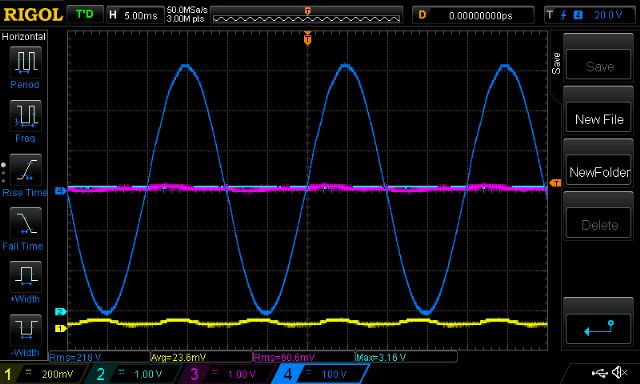 its when a proper load appears we see the E core ferrite find it's all too much and saturate. 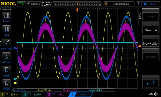 This also has the output AC waveform fairly well distorted too. The PWM current swing during peak AC voltage is about 700mV or 17 Amps. Once a decent amount of current pre-exists in the inductor, any transient current sees a much less inductance. The E core is a TDK E 65/32/27 RS part no. 840-7727. The spec sheet from RS weebsite shows A(L) value is 7200nH i.e. 7.2uH per turn2, so 5 turns means 5x5x7.2 = about 180uH Just as the LCR meter confirms. wronger than a phone book full of wrong phone numbers |
||||
| Solar Mike Guru Joined: 08/02/2015 Location: New ZealandPosts: 1162 |
I certainly can't, too many projects as it is, but I'm going to build this on a bit of strip board, and some heavy copper foil bars to a large screw terminal low esr cap I happen to have sitting on the shelf, seems the bigger Cap the better. Poida, I have the same ECore, think it will require an air gap to prevent the saturation at your selected Amp Turns value, thin piece mylar film etc, guess this will lower the AL value though, so more turns required. Cheers Mike |
||||
| Tinker Guru Joined: 07/11/2007 Location: AustraliaPosts: 1904 |
OK, I have 12 off, 3000Farad @ 2.7V capacitors here. So, these in series gives me 300 Farad @ 34V, would that be enough capacitance?    Klaus |
||||
| poida Guru Joined: 02/02/2017 Location: AustraliaPosts: 1432 |
300F at 27V might be entertaining to watch. I got best results using a mosfet with the smallest Rds(on). This resistance presents as Inductor series resistance and puts a lower limit on the max current you can test it to. wronger than a phone book full of wrong phone numbers |
||||
| Warpspeed Guru Joined: 09/08/2007 Location: AustraliaPosts: 4406 |
There is a much better way to build an inductance tester than that. The problem with that circuit, and others like it, is that all the energy has to come from the power source, and is then dumped into a resistive load. Both the power source and the load need to be ENORMOUS to test any serious kind of choke. A simple practical way to overcome that problem is to recirculate the energy stored in the choke back into a large energy storage capacitor, so the dc power source only has to make up the circuit losses, which can be quite low. So for example, you can easily test a choke that saturates at fifty amps, requiring an adjustable dc power supply that might need to supply only one or two amps.  Both mosfets turn on and off simultaneously at a constant 50/50% duty cycle, but at an adjustable frequency. A suitably large low ESR electrolytic, capable of supplying huge peak current supplies the charging energy into the choke, while both mosfets are on. When both mosfets turn off, the stored energy in the choke returns to the energy storage capacitor through the two shottky diodes. The energy returned will always be very slightly less due to voltage drops in the diodes and resistive losses through the mosfets and dc resistance of the choke. The ramp up time will always be very slightly longer than the ramp down time, because of these unavoidable losses, so the current having ramped down, will sit at zero for a short time before the mosfets turn back on again. So its always safe to use a 50/50% duty cycle to drive this, preferably coming from a flip flop. A high current Hall sensor will be required to monitor the current ramp, as its dc and only goes in one direction, a current transformer will not work. Start out with your main dc supply at zero volts, and your switching frequency set very high for the shortest on interval. Monitor the current waveform on an oscilloscope. Gradually increase the applied dc voltage, and lower the switching frequency until you get a nice big current ramp, that fills the oscilloscope screen. Its then easy to read off the screen the rate of current rise in terms of amps per microsecond at a known applied dc voltage. The rising ramp will be perfectly linear up to some point, where it will then start to bend upwards, which indicates the onset of saturation. The core might even growl or whine due to magnetostiction at that point. Don't get carried away with this ! Remember your mosfets and shottky diodes have a current limit above which they will definitely go bang. Work out what the safe limit is for your test rig, and stay below that. Heat sinking should not be a big issue, as you just wind up the wick, look, and wind it back down again. No need to run it for extended periods at very high power. If you are using a function generator with push button frequency ranges, do not attempt to switch frequency ranges under significant power. Always reduce the dc voltage to zero, change the frequency range, then wind the volts back up. Just pushing a frequency range button will likely blow up your mosfets. Its a very handy tester to have, and very quick and easy to use. But be mindful that its all too easy to tweak things where the peak currents reached are going to be destructive. The energy storage capacitor is going to have a hard life, so use anything you have on hand to start off with, but plan on eventually getting a really good quality high ripple current rated capacitor. Exploding electrolytics can be dangerous, so take care. Best capacitors are the Evox RIFA brand, often available on e-bay. These have awesome specifications. They come in a white plastic case and always have screw terminals. Brand new they are horribly expensive in the larger sizes, but if you are patient, something suitable will turn up on e-bay. Cheers, �Tony. |
||||
| Warpspeed Guru Joined: 09/08/2007 Location: AustraliaPosts: 4406 |
We are going to need a choke that may see a couple of hundred peak amps or more, and while testing at that current is possible, its not really practical. The solution is to test just the magnetic core with its air gap with a larger number of turns than you plan to eventually have. Find out how many ampere turns saturate the core. Its not too difficult to build a choke tester that goes to thirty or fifty amps peak, and that should be more than sufficient for testing just about anything. You don't need to test at high dc voltage. Twenty to thirty volts maximum will be fine, even if the choke is going to be finally used at a much higher voltage. It just means the current will build up more slowly, and you test at a lower switching frequency. A solar buck regulator inductor might run at 300 volts and 20 Khz. Testing it for saturation at 30 volts and 2 Khz will be perfectly valid. Or 15 volts and 1 Khz. So you can very likely use whatever parts you already have to build one of these, and get some very useful results. All jolly good fun. Cheers, �Tony. |
||||
| poida Guru Joined: 02/02/2017 Location: AustraliaPosts: 1432 |
I hear what you are saying Warpspeed. Between the excellent primary current sensor, the simple inductor tester using one FET and the LCR meter I have it covered. Maybe if I have a spare afternoon and a few beers in the fridge I might make the 2 FET tester. Gate drive will be via a disposable arduino, then a level shifter. Today I put the Ecore ferrite in the kitchen oven, baked at 200C to soften the epoxy keeping the two halves together and quiet. Using the 4" grinder I added an air gap of about 1mm with rounded edges in the middle leg of the E. Al = 7.9uH/T2 ungapped, with the roughly ground gap I have now, it's 0.56uH/T2 9 turns gives a measured 48uH. The air gap means saturation will be at much higher currents. Let's see how it goes. (yellow is DC bus current, pink is primary current, blue is AC out, light blue PWM%) this is at idle. not too bad PWM current swing. You can reduce this further with more inductance of course. See some of my previous posts on this subject. The same 7.5W idle power. 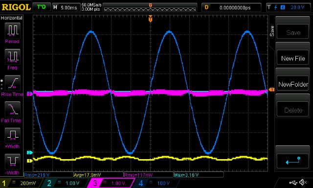 This under load. Note very similar PWM current swing with the higher amps. No saturation now at 435W test load. And a nice looking AC output. Efficiency now 90% (19.3 A, 27.35V gives 440W RMS) 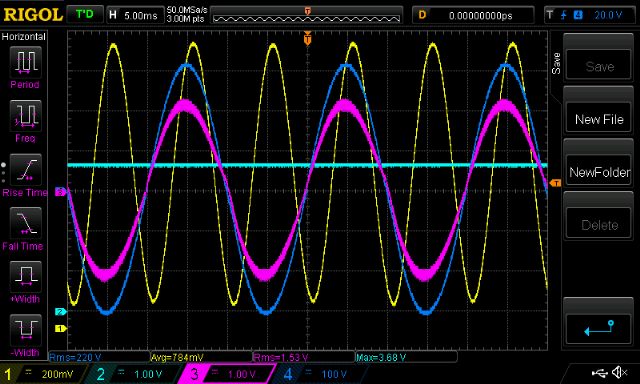 Getting 9 turns of 50mm2 cable through this core will not be possible. I found getting 9 turns of 6mm2 earth wire into it hard enough. The slot dimension is 44 x 12mm So the search for a simple and cheap 50uH choke good for 100 amps continues. Time to look at waveform purity. I calculate the THD of this prototype inverter to be about 0.5% (50Hz 70db, 3rd 25db, 4th 25db, 5th 20db, 6th 20db) via the DSO's FFT. Not too bad at all. 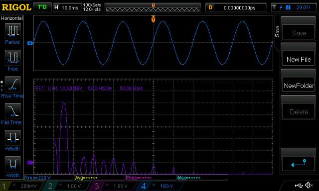 wronger than a phone book full of wrong phone numbers |
||||
| The Back Shed's forum code is written, and hosted, in Australia. | © JAQ Software 2025 |
