
|
|
Forum Index : Microcontroller and PC projects : Micromite eXtreme: New IPS display
| Author | Message | ||||
| matherp Guru Joined: 11/12/2012 Location: United KingdomPosts: 11115 |
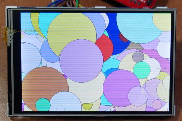 There are quite a few displays now on the market that are designed to work with the Raspberry Pi and these include some higher spec TFTs such as this one which has a 480 by 320 pixel resolution and uses IPS technology which is both brighter and has a better viewing angle than the cheaper TFT panels. The set up of these is quite interesting. The display itself is run in 16-bit parallel mode but the PCB has a couple of 8-bit shift registers so that it can be controlled over an SPI channel as the Raspberry Pi doesn't have an easily accessible 16-bit parallel port. The display is very neat with the viewable area only slightly smaller than the PCB it mounts on. It has the normal XPT2046 touch controller so is fully compatible with the Micromite. The controller on the PCB is an ILI9481 (bigger version of the 9431) and I've included support for this in the MMX code V5.3.14 The command to initialise the display is exactly the same syntax as the ILI9341 OPTION LCDPANEL ILI9481, orientation, DCpin, Resetpin, CSpin Unfortunately, because of the way the display is wired, transparent text and the BLIT command are not available on this display The required connections on the 26-pin header are: Pin-2 5V pin-6 GND pin-11 T_IRQ pin-18 ILI_DC pin-19 SPI2OUT pin-21 SPI2IN pin-22 ILI_RESET pin-23 SPI2CLK pin-24 ILI_CS pin-26 T_CS 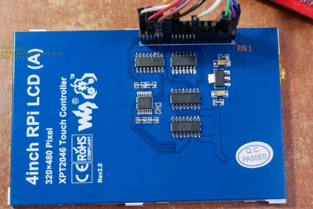 |
||||
| WhiteWizzard Guru Joined: 05/04/2013 Location: United KingdomPosts: 2962 |
Nice display with hopefully much better contrast (as well as better viewing angle). The link you supplied describes it as a 4" screen. Can I kindly ask for some measurements please: 1> PCB sizt 2> Glass size 3> Viewing area size 4>Maximum overall thickness from glass front, to highest component BUT NOT the pin header! 5> Maximum thickness (i.e. with pin header) Thanks  WW |
||||
| matherp Guru Joined: 11/12/2012 Location: United KingdomPosts: 11115 |
PCB 94x61.2 glass - same view 83x54.3 thickness 7.2 thickness+header 18.6 |
||||
| Zonker Guru Joined: 18/08/2012 Location: United StatesPosts: 772 |
I was hoping for a brighter, "daylight" readable unit... I need to check this out..! Thank's Peter..!  |
||||
geraldfryjr Regular Member Joined: 02/03/2014 Location: United StatesPosts: 61 |
Cool, I just ordered Two of them!!!  jer  Keep on DIYin' !!! |
||||
| erbp Senior Member Joined: 03/05/2016 Location: AustraliaPosts: 195 |
Hi, I am looking for clarification as to the wiring for the ILI9481 LCD screen - specifically the SPI connections on Pins 19 and 21 of the LCD header. As listed above, the signal names appear to be the signals they connect to at the MM end. I just want to be sure this is the correct interpretation and the OUT and IN do not refer to the signals from the LCD controller's perspective. Thanks, Phil. |
||||
disco4now Guru Joined: 18/12/2014 Location: AustraliaPosts: 1109 |
The pins I used on an MMX100 are below. It confirms that the labels given refer to the the MM end for SPI2OUT and SPI2IN. The required connections -------My MMX100 on the 26-pin header are:-------pins Pin-2 5V pin-6 GND pin-11 T_IRQ-------------------100 pin-18 ILI_DC-------------------96 pin-19 SPI2OUT------------------66 pin-21 SPI2IN-------------------72 pin-22 ILI_RESET----------------95 pin-23 SPI2CLK------------------10 pin-24 ILI_CS-------------------97 pin-26 T_CS---------------------98 Regards Gerry F4 H7FotSF4xGT |
||||
| erbp Senior Member Joined: 03/05/2016 Location: AustraliaPosts: 195 |
@Gerry Thanks. I don't want to damage my new 4" IPS ILI9481 display (or MM) by having two SPIOUTs trying to drive the same connection. Regards, Phil. |
||||
| Cremo Newbie Joined: 21/07/2015 Location: ItalyPosts: 36 |
Hello, this display seems very interesting. I would like to know if in a near future it will be possible to use it with MM+. Thank you. Pietro |
||||
| matherp Guru Joined: 11/12/2012 Location: United KingdomPosts: 11115 |
See Here |
||||
| Cremo Newbie Joined: 21/07/2015 Location: ItalyPosts: 36 |
Thank you. Pietro |
||||
| The Back Shed's forum code is written, and hosted, in Australia. | © JAQ Software 2026 |
