
|
|
Forum Index : Microcontroller and PC projects : Taming the ACS712
| Author | Message | ||||
TassyJim Guru Joined: 07/08/2011 Location: AustraliaPosts: 6538 |
Over the last few months, I have been playing with a monitor for a small solar charged 12V supply. It started out OK but then I got too involved with trying to get accurate readings from sensors that were never designed for precision. My efforts might help others who use the ACS712 current sensors. The ACS712 is a 5V device and with zero amps, it's output is at half VCC or 2.5V I decided on 30A modules and wired the primary circuits so that increasing amps gives a reducing voltage output. This means that I can handle +30 amps and -11 amps without going off scale. There should never be -ve amps on the solar side but when the AC charger is running, it will be back feeding into the battery at a maximum of 12 amps minus the load of at least 1.1 amps. That's close but not too close. The charge would only put out 12 amps while the battery is very flat and that shouldn't happen. I wired the charger directly to the fuse panel so that the battery can be fully disconnected while having the load maintained. 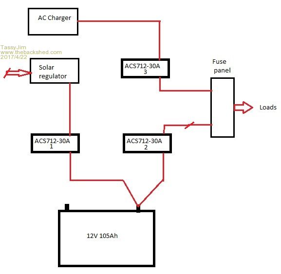 I started with the two ASC712 modules for solar and load. The readings were good for a few days then the zero amps started to wander. The output of the modules is temperature sensitive so I added a DS18B20 and did the calibration maths. It worked, sort of, but still not happy. The other cause of reading errors could have been fluctuation in the 5v supply to the modules or the 3.3V supply to the micromite. A pair of 10k resistors across the 5V supply and used as a reference would eliminate both sources of error but I decided to use a third ASC712 as the zero current reference. That worked beautifully and over a few weeks and a range of temperatures, the solar zero current was consistent as well as the base load current of the load. Happy days! But since I had the ACS712 doing nothing, I wired it into the AC charger output. Now the third module is used as the zero reference whenever the charger is off and the last zero is used for the time that the charger is running. The maximum run time for the charger has been set to 2 hours so for that period of time, the current readings will be off slightly but after a few weeks of monitoring, I am happy. The code is reasonably basic. There is no LCD to admire, just a serial link to my network. A program on my PC will eventually fetch readings periodically during the day and occasionally adjust the micromite's clock. ON the micromite, I have 2 arrays, one for today and the other for yesterday. The day is divided into 96 15 minute intervals. Provided the PC connects every 48 hours, no data is lost. At the start of a new day, the daily stats are saved into a weekly array. The solar regulator (a cheap ebay one) uses a slow PWM with a frequency of 10 to 25 Hz. This slow switching keeps the strain of the switching transistors but makes taking a reading awkward. I ended up taking 100 readings over 600mS and averaging them. As well as giving a stable reading, it allowed me to record the maximum reading of the 100 samples and use that as the available solar output for the reading. Readings are taken every 10 seconds and placed into their time-slot of the array. It is done in a way that will always have the average for that time-slot, no matter how many readings have been entered. After the readings are taken and stored, the logic for controlling the AC charger is run. The charger is controlled by RF and an Arlec switch which is not 100% reliable so I needed to check the current and if I think that there should be some charging current but there is none, resend the ON command. This test happens every 10 seconds so even if there has been an AC fail, we are not likely to spend too much time trying to turn the charger on. Likewise when the 2 hours are up. If there is still current flowing, send an OFF command again. So far, I have been charting the output in Excel 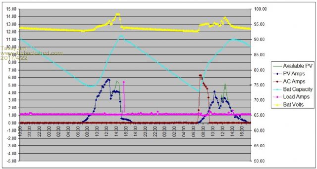 On the first day, the dip in the solar output is caused by the shadow from a tower. You can see the green trace of the maximum solar in the second hump of day one. The regulator was starting to limit the current as the voltage rose to 14.3V At about 4pm the solar panel is shaded by trees. About then the transmitter was used and the load increased for a while. It normally sits on 1.1A when on standby. At 7am on day 2, the battery voltage dipped below 12V so the AC charger (Brown trace) came on for 2 hours. Just as well because it was cloudy that day so not much solar contribution. Still enough to do a bit of regulating. The cyan trace is the estimated remaining capacity, not something to take too seriously. 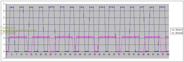 This graph shows the PWM of the solar regulator for two different conditions and the 100 readings used to record it. the full time shown is about 600mS The full program 2017-04-22_045614_RTVmonitor.zip The communications side is designed for a multidrop setup. All commands must start with $9 (this module) or $0 (broadcast to all modules). Jim VK7JH MMedit |
||||
| paceman Guru Joined: 07/10/2011 Location: AustraliaPosts: 1329 |
Very nice job Jim - looks like you've nailed it. Plenty for us all to ponder here. Greg |
||||
| TassyJim Guru Joined: 07/08/2011 Location: AustraliaPosts: 6538 |
No. The hard part is convincing the Boss that we need a second solar panel on the eastern side of the garage roof. Where she can see it from the house. VK7JH MMedit |
||||
| paceman Guru Joined: 07/10/2011 Location: AustraliaPosts: 1329 |
Hmmmm... tricky! She seemed like a very nice lady when we all met up so I think you'll have to go gently - more chocolate perhaps?  |
||||
| The Back Shed's forum code is written, and hosted, in Australia. | © JAQ Software 2026 |
