
|
|
Forum Index : Microcontroller and PC projects : 3v input problem....
| Page 1 of 2 |
|||||
| Author | Message | ||||
Grogster Admin Group Joined: 31/12/2012 Location: New ZealandPosts: 9975 |
Hello folks.  I have a 5v TTL RF receiver connected to COM3 on the E100(via CLICK 1 socket), which is a 3v3 input. The E100 has a 1k series resistor on this line(R11), and all is working fine with the 5v input, but I figured it might be safer to put a potential-divider in front of that input, to keep the voltage within the 3v3 specs, so I built this: 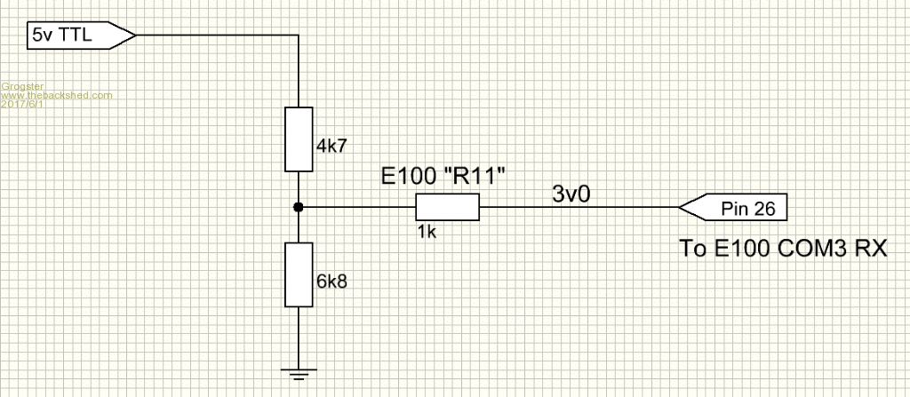 ...but I then get no response from the system.  The voltage on COM3 RX is 3v0, which is spot-on within spec, so I would have expected it to work?  (electrical specs of the manual say a logic-high is >=2v5) (electrical specs of the manual say a logic-high is >=2v5)I have an E64 where I do this, but it does NOT have the 1k "R11"(just the potential-divider - in that case 2k2/4k7), and this idea works just fine on that one, so it must be something to do with the 1k series resistor, but I can't see HOW this is stopping it. For now, I have gone back to the 5v input on COM3 via CLICK 1 socket. Can anyone offer any explanation, as I am scratching my head at the moment.... Smoke makes things work. When the smoke gets out, it stops! |
||||
BobD Guru Joined: 07/12/2011 Location: AustraliaPosts: 935 |
Grogs does the voltage on pin 26 hold up when you define it as a digital input? If not then you may have to lower your 4k7 and 6k8 resistors and / or remove the 1k resistor. I don't know what load the PIC has on the line but it may be dragging the signal down more than 0.5 volts. You can afford to lower your resistors since you are dragging about 40 microamps through the divider. Bob |
||||
bigmik Guru Joined: 20/06/2011 Location: AustraliaPosts: 2981 |
Grogs, I think the divider alone might work (scrub the 1k) but you might be better off with just the 1k direct from the 5V RF output to Pin26. If you were really concerned clamp pin26 with a diode that has the ANODE at pin 26 and the CATHODE at Vcc using a 1N5817 (or IN5819) SCHOTTKY diode. Kind Regards, Mick Mick's uMite Stuff can be found >>> HERE (Kindly hosted by Dontronics) <<< |
||||
TassyJim Guru Joined: 07/08/2011 Location: AustraliaPosts: 6538 |
Measure the 'low' voltage on the pin. I expect that the internal pullup is preventing it going low enough. 1k series without the potential divider is usually reliable. Jim VK7JH MMedit |
||||
| Grogster Admin Group Joined: 31/12/2012 Location: New ZealandPosts: 9975 |
Okey dokey, I will leave it as it is. I seem to recall reading somewhere that you should not apply 5v logic to 3v3 input pins - even with the 1k series resistor - without some kind of level-correction. It is quite likely I am just being over-cautious, but better that then..... Smoke makes things work. When the smoke gets out, it stops! |
||||
| JohnS Guru Joined: 18/11/2011 Location: United KingdomPosts: 4335 |
Do you actually have the internal pull-up enabled? If yes, try it without. (Unless you need it.) John |
||||
| Grogster Admin Group Joined: 31/12/2012 Location: New ZealandPosts: 9975 |
No, I don't. It is the COM3 input pin, so unless this command pulls it up in the background..... The RXD output from the RF module is idle-high via 10k anyway. Goes perfectly without the divider and just using the built-in 1k series resistor, but it just makes me a little anxious applying 5v to what is technically a 3v3 input.  Smoke makes things work. When the smoke gets out, it stops! |
||||
| Geoffg Guru Joined: 06/06/2011 Location: AustraliaPosts: 3362 |
There is an internal weak pullup applied on COM3 when it is opened and that is probably the cause. You can disable this by installing the ChangePin CSub (included in the Micromite zip) and using it like this: ChangePin 26, 15 You are right to be anxious about using only the 1K resistor. It was assumed that protection diodes on the input (most micros have them) would clamp the voltage to Vdd but with further investigation I have found that on the PIC32 there are no protective diodes and no clamping. The best way to go would be to use an external general purpose diode (eg, 1N4148) from pin 26 to Vdd to clamp the input. An alternative would be to use a voltage divider as you did and turn off the pullup. Geoff Geoff Graham - http://geoffg.net |
||||
| JohnS Guru Joined: 18/11/2011 Location: United KingdomPosts: 4335 |
Thanks. John |
||||
| Grogster Admin Group Joined: 31/12/2012 Location: New ZealandPosts: 9975 |
Thanks from me too - I will use the change-pin CSub and have another play with the divider tomorrow. Smoke makes things work. When the smoke gets out, it stops! |
||||
redrok Senior Member Joined: 15/09/2014 Location: United StatesPosts: 209 |
Hi Grogster; 1. What is the voltage on pin(26) when the RF Module output is at 0V? 2. Is it possible that RF Module is not outputting what you expect? I.e 5V and 0V? 3. What do the signals look like on an O-Scope? redrok AD0TJ |
||||
| Grogster Admin Group Joined: 31/12/2012 Location: New ZealandPosts: 9975 |
Hi redrok - nice to see you around the forums again. 1) 3v0. This is cos there is a 10k pullup on the receiver to the 5v supply, subsequently COM3 RX(pin 26) is idle 3v0 via the potential divider. 2) Certainly possible, but it works just fine without the divider, and I have used these modules on several projects(with a PICAXE data-filter) and they always work fine. 3) Don't know.  I need to bring home my scope from the workshop. It is probably more use here then at the workshop these days! I need to bring home my scope from the workshop. It is probably more use here then at the workshop these days!  Smoke makes things work. When the smoke gets out, it stops! |
||||
| Grogster Admin Group Joined: 31/12/2012 Location: New ZealandPosts: 9975 |
UPDATE: The CSub worked! I did change the command to: ChangePin 26,13 'Disable internal pullup on COM3 RX - See ChangePin CSub PDF. But that done, it works perfectly fine with the potential divider AND the series 1K resistor on the E100 board. Thanks for the prod in the direction of that CSub, Geoff.  Smoke makes things work. When the smoke gets out, it stops! |
||||
| redrok Senior Member Joined: 15/09/2014 Location: United StatesPosts: 209 |
Hi Grogster; That begs the question: Since the weak pull up is 60K and the RF Module is outputting 0V the PIN(26) should see about 0.176V. Clearly this would still look like a low. Something else besides the 60K pull up is not right. The 60K shouldn't have any effect at all. Since the 60K does have an effect something is on the harry edge. I bet the RF module is not pulling its output to 0V. Maybe a lot higher. Is the RF Module ground directly connector to the uMITE ground? OK, the spec says the thresholds are 25% and 75% of 3.3V. But seriously, I've never seen any pin that didn't switch more than a few % away from 50% or about 1.65V. redrok AD0TJ |
||||
| Grogster Admin Group Joined: 31/12/2012 Location: New ZealandPosts: 9975 |
Hey there. There is a 10k external pullup on the receiver board. This is separate from the receiver itself. This pulls up the data line to 5v at any time that the receiver module is NOT pulling the line down, so it stays idle high via the 10k resistor, even if the receiver is outputting 0v, if you see what I mean. This is simply to prevent the line floating and being susceptible to rouge data, I expect - just about any receiver you look at, has some form of pullup on the RXD line. Smoke makes things work. When the smoke gets out, it stops! |
||||
GoodToGo! Senior Member Joined: 23/04/2017 Location: AustraliaPosts: 188 |
Nothing worse than being susceptable to rouge data  Even Baz would agree with his new, soon to be released behind the scenes look at Programming in the Movies. I here it's gonna be called Moulin Rouge Data. Cheers, GTG!  ...... Don't worry mate, it'll be GoodToGo! |
||||
| BobD Guru Joined: 07/12/2011 Location: AustraliaPosts: 935 |
not all of us are great at spelling but you brought up Moulin Rouge. My wife's brother and his wife had an invite to a wedding in Carmarthen, Wales UK recently. The theme was Moulin Rouge. It made the local papers and the sister in law got caught in the video at exactly 1 minute in for about 2 seconds. This will give you a giggle. http://www.walesonline.co.uk/news/wales-news/amazing-video-shows-moulin-rouge-13073878 |
||||
| Grogster Admin Group Joined: 31/12/2012 Location: New ZealandPosts: 9975 |
Whoops! Typo!  I meant "Rogue data", naturally. Smoke makes things work. When the smoke gets out, it stops! |
||||
| GoodToGo! Senior Member Joined: 23/04/2017 Location: AustraliaPosts: 188 |
Top stuff! Looks like everyone had a good time. Makes a welcome change from the usual Day-in-Day-out kind of wedding. GTG! ...... Don't worry mate, it'll be GoodToGo! |
||||
| TassyJim Guru Joined: 07/08/2011 Location: AustraliaPosts: 6538 |
I did some experimenting for peterm a few weeks ago. I think it was for the MMX but probably is the same for the micromite and micromite plus. The internal pullup appears to be a lot lower value than 60k. I will look up my notes when I get back home in a few weeks. I had a quick look through the posts here but couldn't find the one where it was discussed. Jim VK7JH MMedit |
||||
| Page 1 of 2 |
|||||
| The Back Shed's forum code is written, and hosted, in Australia. | © JAQ Software 2026 |
