
|
|
Forum Index : Microcontroller and PC projects : user display using arduino front end
| Author | Message | ||||
| isochronic Guru Joined: 21/01/2012 Location: AustraliaPosts: 689 |
I have been trialling using a lcd for a while. The intent is for a small display for user on-going info and simple control via selections etc. [The background idea was, to separate the display/presentation tasks from the main processing, but to keep the information/context on the screen tightly bound with the machine state changes and user control - well that is the excuse.  ] ]A simple protocol is all that is needed, I used SPI (that is, serial peripheral interface, not espionage  ) and it is working OK. So, a client display hangs off the main pcb on a spi port and has data sent to it, and sends back the user selections etc as they are made. ) and it is working OK. So, a client display hangs off the main pcb on a spi port and has data sent to it, and sends back the user selections etc as they are made.In this case the main board is a pic32mx170 running a simple A/D acquisition on two pins, corresponding to say voltage and current measurements. (A "burst" A-D mode can be used for much faster data acquisition, or say a pic32MZ instead obviously). CALL acquiredat ( dat ) ... CALL tekplot ( dat, xmin, ymin, xmax, ymax, res ) ... SUBROUTINE acquiredat ( acdat ) C Can be two channels INTEGER*4 i, k DO 20 i = 1, 120 acdat(i,1) = ADX1 20 acdat(i,2) = ADX0 RETURN END The program scales and sends data to the display via spi exchange, as sequential y data points (mm). ... DO WHILE ( i < 121 ) val = FLOAT ( dat(i,1) ) val = val * sclfac mm = IFIX val + 32 ... CALL xsptek ( nn, mm, bt ) ... The default sends the two channels as two lines. The data is offset 32 to move it out of the ASCII control codes. The display program is directed by some embedded control codes. 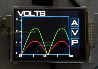 The user can select option A,V,P (amps, voltage,power) on the touchscreen and the choice is sent back to the main program. This alters the program flow accordingly. So, if "P" (power) is selected, instead of the volt and amp values being sent, the program multiplies the two data points (amps, volts) to give the power value, and the result is scaled and sent. DO WHILE ( i < 121 ) val = FLOAT ( dat(i,1) ) * sclfac val = FLOAT ( dat(i,2) ) * sclfac * val val = val * 0.02 mm = IFIX val + 32 ... and the display now shows the power instead 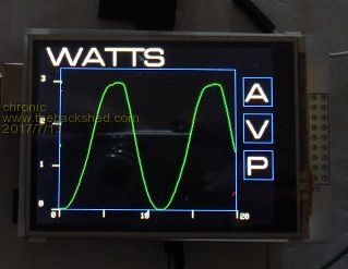 it seems to working OK so far. The main board is a generic one I built with a pic32mx170 and smd components from Altronics, the display is a 240x320 lcd from Jaycar, which uses an arduino shield driving the parallel address pins, and the screenscraper client is a C program running on the uno. I can see a Microchip pic32mzDA being used here as well in future, I will wait for the trail-blazers though !! |
||||
| isochronic Guru Joined: 21/01/2012 Location: AustraliaPosts: 689 |
Although GUI/Net-world has controls and scripts eg for user i/o handling, there does not seem to be a simple standard protocol established for micros, for displaying a small meter or gauge and updating it, that would make these things more transferable (?) and separable. It would make development easier I think. So as a very provisional start, here is what working so far - - the main program runs user i/o via a spi port (eg instead of serial/rs232) - it sends data and embedded control codes - the display program is a screenscraper on a small micro - it runs as a spi slave (client), 8 or 16 bit, with the spi port interrupt driven, loading a fifo buffer - the non-interrupt task reads the buffer, interprets the control codes and presents the data updating the display modules (and feeding user choices back as appropriate) - it updates every second or so (it can be a lot faster but I still have a lot of delays built in for development) I am using a 16 bit slave but 8 bits would be ok for many situations. A byte can be used as a numeric value eg values up to 256. For convenience the first 32 can be used as the ascii control codes, to direct the top level "container" or screen, (eg to clear the screen, switch to graphic mode or activate the next object). The data values in the range 0-220 then use the rest of the range, using a simple offset, leaving a few that can be interpreted by the individual display object in focus. So, initially the screen is in text mode and types ascii characters as per serial terminal. When a GS is received it switches to graphic mode, the next bytes from the buffer are used and displayed by the first graphic object (green line). An embedded control code switches focus to the next graphic (red line), the next embedded control code switches back to the screen handling etc. In practice the viewer can only see or need up to 200 increments on a scale, and individual display objects could use many more control codes, so I suggest a data range of 200 which would leave approx 16 control codes for the objects use. Instead of a line, a meter or gauge type graphic could be used. A different object type could simply display a numeric value and so on. Each type can use the data sequence as required. The data transfer should have some sort of checksum though, maybe CAN bus or similar is the way to go but it looks complex. The overall point is, this allows the main program to be kept in use even though the display screenscraper can change on a separate agenda. A generic arduino display is very useful, and can be replaced by a similar pic32mzDA version in future, without having to rewrite the main program. |
||||
| isochronic Guru Joined: 21/01/2012 Location: AustraliaPosts: 689 |
Using "burst" mode to sample and digitize is better - eg SUBROUTINE acquiredat ( acdat ) C acdat is two dimensional array ZADACQ acdat RETURN END where zadacq is a c routine that digitises two channels and fills the array. The screen here is displaying a 10kHz signal on the two input channels, with the screen about a millisecond wide. The pic32mx170 A/D can be pushed a fair bit further if needed but that is not intended here. 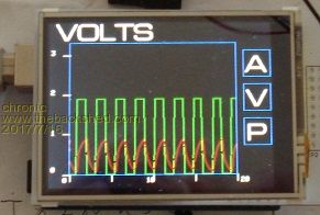 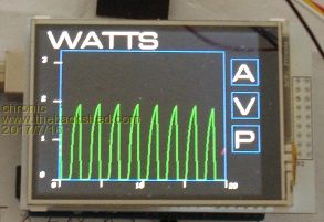 so I guess that is proof of concept OK. After reviewing a bit I think the best options are - -leave it as 16 bit SPI -use the byte range 0-255 -- 0<->32 as the main screen "container" direction characters -- offset the data points past the initial 32 -- use a range of 200 -- leave the last 16 or so as directing codes for individual object use So far: main screen container mode: (default) ESC (escape) resets screen and initializes FF (form feed) wipes the screen TAB (tab) sets focus to next graphic object CR/LF (carriage return)/(line feed) new line in text field GS (group separator) starts graphic mode in graphic object mode: (253) sets focus to next graphic object (254) control back to container screen I need to set a definite limit on this though as it has too much possible scope. A question is, is there likely to be a spi slave(client) included in the Micromite range ? |
||||
| Zonker Guru Joined: 18/08/2012 Location: United StatesPosts: 772 |
Thank you Stuart..!! Looks looks like an excellent addition... So, with this, we could make a generic display "slave" PCB unit and just plug it in to any project...  (nice)... (nice)... |
||||
| isochronic Guru Joined: 21/01/2012 Location: AustraliaPosts: 689 |
The default text mode is useful as a plain display. The arduino does the screen stuff leaving the pic free for the numeric work. As a trial I hooked up the pic ('170) to a GPS (serial 9600), using current latitude/longitude/time as inputs to calculate solar elevation and azimuth, and sending the text output to the arduino/lcd via a spi port. It updates every second or so, and looks a lot better than the 16x2. (Sorry my photo is blurred  ) )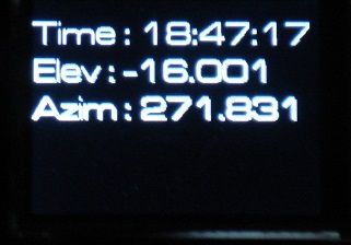 (ed - and yes, the photo is after sunset ) |
||||
| isochronic Guru Joined: 21/01/2012 Location: AustraliaPosts: 689 |
I have produced a small pcb which has the pic32mx170 in a suitable arrangement and thus interconnects the pic32mx170, parallel 240 x 320 lcd shield and genuino / arduino uno. It forms a self-contained stack nicely enough. The whole shebang runs off the uno USB 5v or 9 v socket OK. 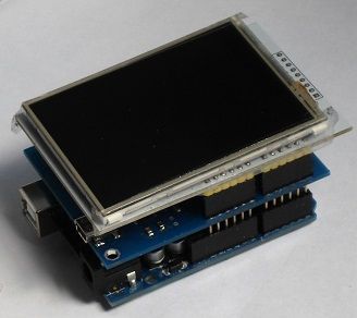 A pin header is on the RHS for data, gps, pickit3 etc. (ed) The pcb is just the pic, two spi port wirings, and the usb-serial link. You can just see the small usb connector on the LHS (middle pcb). |
||||
| robert.rozee Guru Joined: 31/12/2012 Location: New ZealandPosts: 2528 |
looks like a neat hardware solution, though i'm not 100% sure about the software side of things. it isn't mmbasic you're running on the micromite, is it? and what firmware is running on the arduino? something sort of graphical terminal emulation? i have followed the thread, hoping someone else would ask more questions. cheers, rob :-) |
||||
| isochronic Guru Joined: 21/01/2012 Location: AustraliaPosts: 689 |
The pic32mx170 runs the main program, sending info to/from the arduino which drives the lcd and touchscreen. MMBasic would probably run as a serial i/o on the pic (I don't know as yet), might be able to use the spi i/o with a bit of wiring. The arduino program is basically a client sketch that displays info sent to it and returns the touchscreen actions. This means the various public domain libraries etc can be used (note the proportional font )(btw The usb/serial uses a mcp2221..but I did put in links as per pic1455 so your loader might work ) |
||||
| isochronic Guru Joined: 21/01/2012 Location: AustraliaPosts: 689 |
After developing it a bit, - a specific control (object) can be selected for update instead of tabbing - an end-of-data is signaled from the host (EOT) - an "enquire" (ENQ) signal from the host returns a 16bit word with busy/ok and the last key press - There was enough memory etc to set up nine controls (objects) which use defaults - States can be set up and instigated from the host To select a control DV1 (device control 1) is sent, followed by the control number. So to display "hello" in object 1, DC1 is sent, followed by 1, followed by the hello string, followed by the EOT. And so on. 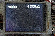 A real value can be sent as a character string. Other control types possible are buttons, a slow sweep or a (ed) cro-snapshot-type display, depending what is sent from the host. (this is some 100Hz ripple, with the voltage at the end of acquisition being also measured and posted as a string) 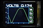 a paragraph-style text field 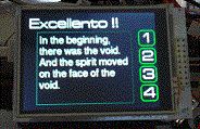 and a menu-style text field that synchronises the text lines to the buttons 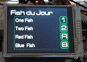 The ino file is available, you will need the Adafruit libraries installed of course and may have/want to use a different font as necessary. ed - You could use this with the 'mites, you will need some easy code to to send bytes out via the spi pins. You will need the spi MOSI, clock and select pins for display at least, and MISO for user interaction (buttons). |
||||
| isochronic Guru Joined: 21/01/2012 Location: AustraliaPosts: 689 |
The board can be useful as a simple pic development/breakout board so I have expanded details of it here |
||||
| isochronic Guru Joined: 21/01/2012 Location: AustraliaPosts: 689 |
A main aim was to make it usable from just about any system that could drive a spi port. (ed) So, the volts 0.174 trace above (leaving out the buttons)..runs using this code, written in an ancient language using simple delays.It would be easy to calculate say actual RMS values on the fly. PROGRAM vitVoltTracespb INTEGER*2 obj, count, adval INTEGER*2 data(120), dd INTEGER*4 i, v DOUBLE voltage, scal CHARACTER*1 num, key, cr CHARACTER*16 val CHARACTER*120 txt FORMAT (F-9.3) WRITE (6,0) obj scal = 3.3 / 1023.0 C pause after startup to wait for other systems CALL startdelay() C start spi port B SPBSTT C set descriptive label in text field obj = 1 txt = 'VOLTS' CALL vitsel ( obj ) CALL vitdat ( txt ) CALL vitgo ( ) C loop DO WHILE ( 1 ) txt = '' C get data as array 'data' of A/D integers CALL acquiredat ( data ) C build string of y integer values as expected by graph. 180 pixels v = 1 DO WHILE ( v < 121 ) num = 'a' - 97 num = num + IFIX ( 180.0 * FLOAT ( data(v) ) / 1023.0 ) + 32 txt = txt + num v = v + 1 END DO C send to graph obj = 8 CALL vitsel ( obj ) CALL vitdat ( txt ) CALL vitgo() C finally get another A/D value, convert to string, C and send it to next text field obj = 2 adval = ADC0 voltage = FLOAT ( adval ) * scal ATDOCC voltage val CALL vitsel ( obj ) CALL vitdat ( val ) CALL vitgo() C loop return END DO END SUBROUTINE vitsel ( ob ) INTEGER*2 dcone, obj, temp dcone = 17 obj = 31 + ob SPBXWD dcone, temp SPBXWD obj, temp CALL delay ( ) RETURN END SUBROUTINE vitdat ( wd ) CHARACTER*16 tempc SPBXWD wd, tempc RETURN END SUBROUTINE vitgo ( ) INTEGER*2 eot, temp eot = 4 SPBXWD eot, temp RETURN END SUBROUTINE delay ( ) INTEGER*4 i i = 1 DO WHILE ( i < 800 ) i = i + 1 END DO RETURN END SUBROUTINE acquiredat ( acdat ) INTEGER*4 i DO 20 i = 1, 120 acdat(i) = ADX0 20 CONTINUE RETURN END SUBROUTINE startdelay ( ) INTEGER*4 i i = 1 DO WHILE ( i < 1000 ) i = i + 1 END DO RETURN END \ |
||||
| isochronic Guru Joined: 21/01/2012 Location: AustraliaPosts: 689 |
This sketch is a standalone demo. It runs on a uno with a parallel drive 240x320 lcd shield eg from Jaycar. In the code, values are put into the buffer artificially instead of from the spi client interrupt. It runs a slow sweep (approx ten seconds) using the analog value from A5. (It is deliberately plain and simple, and is not meant as an example of the best way to achieve a sweep display, but may be of interest.) For this - The buttons are cosmetic only. The touchscreen parameteres will probably have to be tweaked, and I set the font back to a standard one. It is not polished as I have had eyesight probs lately (pending fixing) and it will have to do. The suggested name is Vit10demo1, copy/paste into a new sketch and use "save as" . // Vitrino base 10 beta Demo // // // version 0.95, not perfect but reasonable // // Cut down version for self-running demonstration. // Example shows voltage measurement (A5) as a screen sweep // as well as numeric value. // // Altered for standalone demonstration : // uses standard font, and the input buffer // is filled using adc values instead of using spi transfer // from other systems // // Requires 240x320 lcd (parallel connect) // and the Adafruit libraries as per lcd, // the Adafruit LCD advisory is used // // Initial part of trace is left on screen as visual history // Assumes 5v rail is actually 5v as reference so // measurement accuracy depends on that, unlikely to // be better than a percent or so. // // Supplied for demonstration only. Use at own risk. Do not use // in situations where any hazard, damage, or liability may occur. // Stuart Oliver, Oct/Nov 2017 // #include <Adafruit_GFX.h> // Core graphics library #include <Adafruit_TFTLCD.h> // Hardware-specific library #include <TouchScreen.h> #include <SPI.h> //#include <Fonts/microgmm18pt7b.h> #include <Fonts/FreeSans12pt7b.h> #include <Fonts/FreeSans18pt7b.h> #include <stdint.h> #define LCD_CS A3 #define LCD_CD A2 #define LCD_WR A1 #define LCD_RD A0 // optional #define LCD_RESET A4 #define YP A3 // must be an analog pin, use "An" notation! #define XM A2 // must be an analog pin, use "An" notation! #define YM 9 // can be a digital pin #define XP 8 // can be a digital pin TouchScreen ts = TouchScreen(XP, YP, XM, YM, 300); #define BLACK 0x0000 #define BLUE 0x001F #define RED 0xF800 #define GREEN 0x07E0 #define CYAN 0x07FF #define MAGENTA 0xF81F #define YELLOW 0xFFE0 #define WHITE 0xFFFF #define DIM 0x052F #include <MCUFRIEND_kbv.h> MCUFRIEND_kbv tft; char btnchar = '?'; byte volatile backstat = 'X'; byte inbyte1, inbyte2 ; int ytemp ; volatile byte sched ; byte nthrecin = 0; byte nthrecout = 0 ; byte recflag = 0; char state = '\0' ; byte iobuff [294]; int unsigned innth = 0 ; int unsigned oldnth = 0; struct gobj { byte obtype; int xloc; int yloc; int xsize; int ysize; char oldtxt[16] = " "; char newtxt[16] = " "; union { byte flgs; struct { unsigned int text : 1 ; unsigned int flgb : 1 ; unsigned int flgc : 1 ; unsigned int flgd : 1 ; unsigned int seal : 1 ; unsigned int enabled : 1 ; unsigned int visible : 1 ; unsigned int repaint : 1 ; } flags ; } ; } screen [9] ; int darkry, darkoldry, linepos ; int xl, xy, rx, oldrx, i, j ; int yl, ry, oldry ; volatile byte dark [240] ; volatile byte lite [120] ; volatile byte stage [120] ; #define obj1 screen[0] #define obj2 screen[1] #define obj3 screen[2] #define obj4 screen[3] #define obj5 screen[4] #define obj6 screen[5] #define obj7 screen[6] #define obj8 screen[7] #define obj9 screen[8] byte numobj = 0 ; byte numbtnobj = 0 ; byte maxobj = 0 ; char tempchar ; byte flgnum ; volatile byte countin = 0 ; byte count = 0 ; byte nthtrace = 0 ; int adint; float adfloat; char adstr[6] ; void setup() { randomSeed(analogRead(5)); //.kbv Due does not like A0 pinMode(A0, OUTPUT); //.kbv mcufriend have RD on A0 digitalWrite(A0, HIGH); Serial.begin(115200); // tft.setFont(µgmm18pt7b); tft.setFont(&FreeSans18pt7b); tft.setCursor(20, 50); tft.setTextColor(WHITE); tft.reset(); uint16_t identifier = tft.readID(); if (identifier == 0x9325) { Serial.println(F("Found ILI9325 LCD driver")); } else if (identifier == 0x9328) { Serial.println(F("Found ILI9328 LCD driver")); } else if (identifier == 0x4535) { Serial.println(F("Found LGDP4535 LCD driver")); } else if (identifier == 0x7575) { Serial.println(F("Found HX8347G LCD driver")); } else if (identifier == 0x9341) { Serial.println(F("Found ILI9341 LCD driver")); } else if (identifier == 0x7783) { Serial.println(F("Found ST7781 LCD driver")); } else if (identifier == 0x8230) { Serial.println(F("Found UC8230 LCD driver")); } else if (identifier == 0x8357) { Serial.println(F("Found HX8357D LCD driver")); } else if (identifier == 0x0101) { identifier = 0x9341; Serial.println(F("Found 0x9341 LCD driver")); } else { Serial.print(F("Unknown LCD driver chip: ")); // rest is commented out to save prgram space // Serial.println(identifier, HEX); // Serial.println(F("If using the Adafruit 2.8\" TFT Arduino shield, the line:")); // Serial.println(F(" #define USE_ADAFRUIT_SHIELD_PINOUT")); // Serial.println(F("should appear in the library header (Adafruit_TFT.h).")); // Serial.println(F("If using the breakout board, it should NOT be #defined!")); // Serial.println(F("Also if using the breakout, double-check that all wiring")); // Serial.println(F("matches the tutorial.")); identifier = 0x9341; } tft.begin(identifier); tft.setRotation(1); tft.fillScreen(BLACK); tft.setCursor(20, 50); tft.setTextColor(WHITE); buildscreen(); boilerplate(); memset(stage, ' ', 120); sched = 0 ; backstat = 'X' ; btnchar = '?' ; // have to send on master in, *slave out* pinMode(MISO, OUTPUT); // turn on SPI in slave mode SPCR |= _BV(SPE); // turn on interrupts SPCR |= _BV(SPIE); SPDR = btnchar ; for ( numobj = 0; numobj < maxobj; numobj ++ ) { memset(screen[numobj].newtxt, '\0', 16); memset(screen[numobj].oldtxt, '\0', 16); } initscreen(); //String stringOne = String(analogRead(5), DEC); // Serial.println(stringone); } // SPI interrupt routine here // bypassed ISR (SPI_STC_vect) { // } void loop() { if (sched == 0 ) { TSPoint p = ts.getPoint(); if (p.z > ts.pressureThreshhold) { pinMode(XM, OUTPUT) ; pinMode(YP, OUTPUT) ; // Probably need tweaking for individual touchscreen here ytemp = p.y ; p.y = map ( p.x, 150, 850, 0, 240 ) ; p.x = map ( ytemp, 150, 850, 0, 320 ) ; //Serial.print("X = "); Serial.println(p.x); //Serial.print("Y = "); Serial.println(p.y); for ( numbtnobj = 0; numbtnobj < maxobj; numbtnobj ++ ) { if (( screen[numbtnobj].obtype == 2 ) && ( screen[numbtnobj].flags.enabled == 1 ) && ( screen[numbtnobj].flags.visible == 1 )) { if (( p.x > screen[numbtnobj].xloc ) && ( p.x < (screen[numbtnobj].xloc + screen[numbtnobj].xsize) )) { if (( p.y < screen[numbtnobj].yloc ) && ( p.y > (screen[numbtnobj].yloc - screen[numbtnobj].ysize) )) { btnchar = screen[numbtnobj].oldtxt[0]; tft.setCursor(screen[numbtnobj].xloc + 6, screen[numbtnobj].yloc - 10); tft.setTextColor(RED); tft.print(screen[numbtnobj].newtxt); delay(50); tft.setCursor(screen[numbtnobj].xloc + 6, screen[numbtnobj].yloc - 10); tft.setTextColor(WHITE); tft.print(screen[numbtnobj].newtxt); // Serial.println(btnchar); } } } } } pinMode(XM, OUTPUT) ; pinMode(YP, OUTPUT) ; } else if (sched == 1 ) { distrib(); sched = 2; } else if (sched == 2 ) sched = 3; else if (sched == 3 ) { sched = 4 ; } else if (sched == 4 ) sched = 5; else if (sched == 5 ) { updatescreen(); sched = 6; } else if (sched == 6 ) sched = 0; // demo - puts command/data sequence into the input buffer if ( sched == 0 ) { recflag ++ ; if ( recflag == 20 ) { adint = analogRead(5) ; adfloat = 5.0 * float(adint)/1023.0 ; if ( adfloat > 3.1 ) adfloat = 3.3 ; dtostrf(adfloat,5,3,adstr); iobuff[innth++] = inbyte1 ; iobuff[innth++] = 17 ; countin ++; iobuff[innth++] = inbyte1 ; iobuff[innth++] = 33 ; countin ++; iobuff[innth++] = inbyte1 ; iobuff[innth++] = adstr[0] ; countin ++; iobuff[innth++] = inbyte1 ; iobuff[innth++] = adstr[1] ; countin ++; iobuff[innth++] = inbyte1 ; iobuff[innth++] = adstr[2] ; countin ++; iobuff[innth++] = inbyte1 ; iobuff[innth++] = adstr[3] ; countin ++; iobuff[innth++] = inbyte1 ; iobuff[innth++] = adstr[4] ; countin ++; iobuff[innth++] = inbyte1 ; iobuff[innth++] = '\0' ; countin ++; sched = 1 ; } if ( recflag == 40 ) { iobuff[innth++] = inbyte1 ; iobuff[innth++] = 17 ; countin ++; iobuff[innth++] = inbyte1 ; iobuff[innth++] = 38 ; countin ++; iobuff[innth++] = inbyte1 ; iobuff[innth++] = adstr[0] ; countin ++; iobuff[innth++] = inbyte1 ; iobuff[innth++] = adstr[1] ; countin ++; iobuff[innth++] = inbyte1 ; iobuff[innth++] = adstr[2] ; countin ++; iobuff[innth++] = inbyte1 ; iobuff[innth++] = adstr[3] ; countin ++; iobuff[innth++] = inbyte1 ; iobuff[innth++] = adstr[4] ; countin ++; iobuff[innth++] = inbyte1 ; iobuff[innth++] = '\0' ; countin ++; sched = 1 ; recflag = 0 ; } } } void distrib() { count = 0 ; volatile byte nthob = 0 ; while (oldnth != innth) { if (iobuff[oldnth + 1] != '\0' ) { if (iobuff[(oldnth + 1)] == 9 ) // h-tab { nthob ++; count = 0 ; } else if (iobuff[(oldnth + 1)] == 17 ) //DC1, set obj { count = 0 ; nthob = iobuff[(oldnth + 3)] - 32; iobuff[oldnth ++] = '\0' ; iobuff[oldnth ++] = '\0' ; } else if (iobuff[(oldnth + 1)] == 18 ) // DC2, set state { count = 0 ; state = iobuff[(oldnth + 3)] - 32; iobuff[oldnth ++] = '\0' ; iobuff[oldnth ++] = '\0' ; switch (state) { case 'A' : act_stateA(); break ; case 'B' : act_stateB(); break ; case 'C' : act_stateC(); break ; case 'D' : act_stateD(); break ; default : break ; } } else if (iobuff[(oldnth + 1)] == 19 ) // deprecated, DC3 calls state c { count = 0 ; act_stateC(); } else if (iobuff[(oldnth + 1)] == 20 ) // DC4 , toggles obj flag bit { count = 0 ; flgnum = iobuff[(oldnth + 3)] - 32; iobuff[oldnth ++] = '\0' ; iobuff[oldnth ++] = '\0' ; switch (flgnum) { case 1 : screen[nthob].flags.text ++ ; break ; case 2: screen[nthob].flags.flgb ++ ; break ; case 3: screen[nthob].flags.flgc ++ ; break ; case 4: screen[nthob].flags.flgd ++ ; break ; case 5: screen[nthob].flags.seal ++ ; break ; case 6: screen[nthob].flags.enabled ++ ; ; break ; case 7: screen[nthob].flags.visible ++ ; break ; case 8: screen[nthob].flags.repaint ++ ; break ; default : break ; } } else if (iobuff[(oldnth + 1)] == 24 ) // clear button { count = 0 ; btnchar = '?'; } else if (screen[nthob].obtype == 3 ) // text block { stage[count] = iobuff[oldnth + 1 ] ; screen[nthob].flags.repaint = 1 ; count ++; screen[nthob].flags.repaint = 1 ; screen[nthob].flags.visible = 1 ; screen[nthob].flags.enabled = 1 ; } else if (screen[nthob].obtype == 4 ) // menu text block { stage[count] = iobuff[oldnth + 1 ] ; screen[nthob].flags.repaint = 1 ; count ++; } else if (screen[nthob].obtype == 6 ) // plot data vector { stage[count] = iobuff[oldnth + 1 ] ; screen[nthob].flags.repaint = 1 ; screen[nthob].flags.visible = 1 ; screen[nthob].flags.enabled = 1 ; count ++; } else if (screen[nthob].obtype == 2 ) // button { if (screen[nthob].flags.seal == 1 ) screen[nthob].newtxt[0] = iobuff[oldnth + 1 ] ; screen[nthob].flags.seal == 0 ; screen[nthob].flags.repaint = 1 ; screen[nthob].flags.visible = 1 ; screen[nthob].flags.enabled = 1 ; count ++; } else { screen[nthob].newtxt[count] = iobuff[oldnth + 1 ] ; screen[nthob].flags.repaint = 1 ; screen[nthob].flags.visible = 1 ; screen[nthob].flags.enabled = 1 ; // objboilerplate(nthob); count ++; } } iobuff[oldnth ++] = '\0' ; iobuff[oldnth ++] = '\0' ; } countin = 0 ; innth = 0 ; oldnth = 0 ; return; } void buildscreen() { // .xloc = x location // .yloc = y location // .xsize = x size // .ysize = y size // .obtype = type // .flags.enabled = enabled state // .flags.visible = visible // .flags.repaint = repaint // obtype 1 alphanumeric field // 2 button // 3 text block // 4 menu text block // 5 sweep // 6 plot // maxobj = number of objects, 1 -> x maxobj = 7 ; obj1.xloc = 10 ; obj1.yloc = 36 ; obj1.obtype = 1 ; obj1.flags.enabled = 1 ; obj1.flags.visible = 1 ; obj2.xloc = 180 ; obj2.yloc = 36 ; obj2.obtype = 1 ; obj2.flags.enabled = 1 ; obj2.flags.visible = 1 ; obj3.xloc = 278 ; obj3.yloc = 86 ; obj3.xsize = 40 ; obj3.ysize = 40 ; obj3.obtype = 2 ; obj3.flags.seal == 0 ; obj3.flags.enabled = 1 ; obj3.flags.visible = 1 ; obj4.xloc = 278; obj4.yloc = 132 ; obj4.xsize = 40 ; obj4.ysize = 40 ; obj4.obtype = 2 ; obj4.flags.seal == 0 ; obj4.flags.enabled = 1 ; obj4.flags.visible = 1 ; obj5.xloc = 278 ; obj5.yloc = 178 ; obj5.xsize = 40 ; obj5.ysize = 40 ; obj5.obtype = 2 ; obj5.flags.seal == 0 ; obj5.flags.enabled = 1 ; obj5.flags.visible = 1 ; obj6.xloc = 278 ; obj6.yloc = 224 ; obj6.xsize = 40 ; obj6.ysize = 40 ; obj6.obtype = 2 ; obj6.flags.seal == 0 ; obj6.flags.enabled = 1 ; obj6.flags.visible = 1 ; obj7.xloc = 30 ; obj7.yloc = 224 ; obj7.xsize = 240 ; obj7.ysize = 182 ; obj7.obtype = 5 ; obj7.flags.enabled = 1 ; obj7.flags.visible = 1 ; obj8.xloc = 30 ; obj8.yloc = 224 ; obj8.xsize = 240 ; obj8.ysize = 184 ; obj8.obtype = 6 ; obj8.flags.enabled = 0 ; obj8.flags.visible = 0 ; obj9.xloc = 30 ; obj9.yloc = 228 ; obj9.xsize = 230 ; obj9.ysize = 180 ; obj9.obtype = 3 ; obj9.flags.enabled = 0 ; obj9.flags.visible = 0 ; return ; } void initscreen() { j = 0; strcpy(obj1.newtxt, "VOLTS" ); strcpy(obj1.oldtxt, "VOLTS" ); strcpy(obj2.newtxt, "?" ); strcpy(obj2.oldtxt, "?" ); strcpy(obj3.newtxt, "a" ); strcpy(obj3.oldtxt, "a" ); strcpy(obj4.newtxt, "b" ); strcpy(obj4.oldtxt, "b" ); strcpy(obj5.newtxt, "c" ); strcpy(obj5.oldtxt, "c" ); strcpy(obj6.newtxt, "d" ); strcpy(obj6.oldtxt, "d" ); tft.setTextColor(WHITE); for ( numobj = 0; numobj < maxobj; numobj ++ ) { if (screen[numobj].flags.visible == 1) { if (screen[numobj].obtype == 1) // 1 = text { tft.setCursor(screen[numobj].xloc, screen[numobj].yloc); tft.println(screen[numobj].oldtxt); } else if (screen[numobj].obtype == 2) // 2 = button { tft.setCursor(screen[numobj].xloc + 6, screen[numobj].yloc - 10); tft.println(screen[numobj].oldtxt); } } } return; } void updatescreen() { byte nxtchr = 0; byte linenum = 1 ; for ( numobj = 0; numobj < maxobj; numobj ++ ) { if ((screen[numobj].flags.repaint != 0) && (screen[numobj].flags.visible == 1)) { if (screen[numobj].obtype == 1) // 1 = alphanumeric field { if ( strcmp (screen[numobj].oldtxt, screen[numobj].newtxt) != 0 ) { nxtchr = 0; tft.setTextColor(WHITE); tft.setCursor(screen[numobj].xloc, screen[numobj].yloc); while ( screen[numobj].oldtxt[nxtchr] == screen[numobj].newtxt[nxtchr] ) { tft.print(screen[numobj].oldtxt[nxtchr]); nxtchr ++ ; } tft.setTextColor(BLACK); while ( screen[numobj].oldtxt[nxtchr] != '\0' ) { tft.print(screen[numobj].oldtxt[nxtchr]); nxtchr ++ ; } tft.setTextColor(WHITE); tft.setCursor(screen[numobj].xloc, screen[numobj].yloc); tft.println(screen[numobj].newtxt); strcpy(screen[numobj].oldtxt, screen[numobj].newtxt); } } else if (screen[numobj].obtype == 2) // 2 = button { if (screen[numobj].flags.enabled == 1) { objboilerplate ( numobj ); tft.setCursor(screen[numobj].xloc + 6, screen[numobj].yloc - 10); tft.setTextColor(WHITE); tft.print(screen[numobj].newtxt); } else if (screen[numobj].flags.enabled == 0) { tft.drawRoundRect(screen[numobj].xloc, (screen[numobj].yloc - screen[numobj].ysize), screen[numobj].xsize, screen[numobj].ysize, 8 , GREEN ); tft.setCursor(screen[numobj].xloc + 6, screen[numobj].yloc - 10); tft.setTextColor(DIM); tft.print(screen[numobj].newtxt); } screen[numobj].flags.repaint == 0 ; } else if (screen[numobj].obtype == 3) // 3 text block (/menu) { nxtchr = 0; tft.setFont(); // tft.setFont(µgmm18pt7b); tft.setFont(&FreeSans12pt7b); tft.fillRect(screen[numobj].xloc + 1, (screen[numobj].yloc - screen[numobj].ysize + 1), screen[numobj].xsize - 2, screen[numobj].ysize - 2, BLACK ); tft.setTextColor(WHITE); tft.setCursor(screen[numobj].xloc + 6, screen[(linenum ++ + 1)].yloc - 10); while ( nxtchr < count ) { tempchar = stage[nxtchr]; if (tempchar == 13) { if ( screen[numobj].flags.text == 1 ) { tft.setCursor(screen[numobj].xloc + 6, screen[numobj].yloc - screen[numobj].ysize + linenum ++ * 28); } else // menu vertical tft.setCursor(screen[numobj].xloc + 6, screen[(linenum ++ + 1)].yloc - 10); } else tft.print(tempchar); nxtchr ++ ; } objboilerplate(numobj); // tft.setFont(µgmm18pt7b); tft.setFont(&FreeSans18pt7b); } else if (screen[numobj].obtype == 4) // 4 text block (menu) { nxtchr = 0; //tft.setFont(); // tft.setFont(µgmm18pt7b); tft.setFont(&FreeSans12pt7b); tft.fillRect(screen[numobj].xloc + 1, (screen[numobj].yloc - screen[numobj].ysize + 1), screen[numobj].xsize - 2, screen[numobj].ysize - 2, BLACK ); tft.setTextColor(WHITE); tft.setCursor(screen[numobj].xloc + 6, screen[(linenum ++ + 1)].yloc - 10); while ( nxtchr < count ) { tempchar = stage[nxtchr]; if (tempchar == 13) tft.setCursor(screen[numobj].xloc + 6, screen[(linenum ++ + 1)].yloc - 10); else tft.print(tempchar); nxtchr ++ ; } tft.setFont(&FreeSans18pt7b); //tft.setFont(µgmm18pt7b); // tft.setFont(&FreeSans12pt7b); } else if (screen[numobj].obtype == 5) // 5 = sweep { objboilerplate(numobj); yl = atof(screen[numobj].newtxt) / 3.3 * 180 ; rx = 31 + j ; ry = 222 - yl ; darkry = dark[j]; if ( j == 0 ) { oldrx = 31 ; oldry = ry ; darkry = ry ; darkoldry = ry ; } tft.drawLine(oldrx, darkoldry, rx, darkry, BLACK); // tft.drawLine(oldrx, oldry, rx, ry, RED//); tft.drawLine(oldrx, oldry, rx, ry, GREEN); oldrx = rx ; oldry = ry ; dark[j] = ry ; darkoldry = darkry ; j++ ; if (j == 239 ) { j = 0 ; } } else if (screen[numobj].obtype == 6) // 6 = trace { j = 0 ; nxtchr = 0 ; objboilerplate(numobj); while ( nxtchr < count ) { yl = stage[nxtchr] - 32; rx = 30 + j * 2 ; ry = 222 - yl ; // if (ry > 200 ) ry = 220 ; darkry = dark[j]; if ( j == 0 ) { oldrx = 30 ; oldry = ry ; darkry = ry ; darkoldry = ry ; } if (nthtrace > 0 ) { tft.drawLine(oldrx, darkoldry, rx, darkry, BLACK); } tft.drawLine(oldrx, oldry, rx, ry, GREEN); oldrx = rx ; oldry = ry ; dark[j] = ry ; darkoldry = darkry ; j++ ; if (j == 120 ) { j = 0 ; nthtrace ++ ; } nxtchr ++ ; } } } } screen[numobj].flags.repaint = 0 ; nthrecin = 0; //memset(stage, '\0', 120); return ; } void act_stateA() { return ; } void act_stateB() { return ; } void act_stateC() { return ; } void act_stateD() { return ; } void boilerplate() { byte numobj ; tft.fillScreen(BLACK); //outlines for ( numobj = 0; numobj < maxobj; numobj ++ ) { if (screen[numobj].flags.visible == 1) { if ( screen[numobj].obtype == 2 ) tft.drawRoundRect(screen[numobj].xloc, (screen[numobj].yloc - screen[numobj].ysize), screen[numobj].xsize, screen[numobj].ysize, 8 , GREEN ); if ( screen[numobj].obtype == 3 ) tft.drawRect(screen[numobj].xloc, (screen[numobj].yloc - screen[numobj].ysize), screen[numobj].xsize, screen[numobj].ysize, RED ); if ( screen[numobj].obtype == 5 ) { tft.drawRect(screen[numobj].xloc, (screen[numobj].yloc - screen[numobj].ysize), screen[numobj].xsize, screen[numobj].ysize, BLUE ); // tft.drawLine(31, 223, 31, 40, BLACK); axetics(); } if ( screen[numobj].obtype == 6 ) { tft.drawRect(screen[numobj].xloc, (screen[numobj].yloc - screen[numobj].ysize), screen[numobj].xsize, screen[numobj].ysize, BLUE ); axetics(); } } } return ; } void objboilerplate ( byte nthob ) { if (screen[nthob].flags.visible == 1) { if ( screen[nthob].obtype == 2 ) tft.drawRoundRect(screen[nthob].xloc, (screen[nthob].yloc - screen[nthob].ysize), screen[nthob].xsize, screen[nthob].ysize, 8 , GREEN ); if ( screen[nthob].obtype == 3 ) tft.drawRect(screen[nthob].xloc, (screen[nthob].yloc - screen[nthob].ysize), screen[nthob].xsize, screen[nthob].ysize, DIM ); if ( screen[nthob].obtype == 5 ) { tft.drawRect(screen[nthob].xloc, (screen[nthob].yloc - screen[nthob].ysize), screen[nthob].xsize, screen[nthob].ysize, BLUE ); //tft.drawLine(31, 223, 31, 40, BLACK); axetics(); } if ( screen[nthob].obtype == 6 ) { tft.drawRect(screen[nthob].xloc, (screen[nthob].yloc - screen[nthob].ysize), screen[nthob].xsize, screen[nthob].ysize, BLUE ); axetics(); } } } void axetics () { tft.setTextColor(WHITE); // vert axis tics tft.drawLine(20, 222, 30, 222, WHITE); tft.drawLine(20, 167, 30, 167, WHITE); tft.drawLine(20, 113, 30, 113, WHITE); tft.drawLine(20, 59, 30, 59, WHITE); //hori tics tft.drawLine(30, 223, 30, 230, WHITE); tft.drawLine(90, 223, 90, 230, WHITE); tft.drawLine(150, 223, 150, 230, WHITE); tft.drawLine(210, 223, 210, 230, WHITE); tft.drawLine(270, 223, 270, 230, WHITE); // tft.print("0", 20, 225); // tft.print("10", 140, 225); // tft.print("20", 260, 225); // tft.print("ms", 275, 215); tft.setFont(); tft.setCursor(3, 210); tft.print("0"); tft.setCursor(3, 155); tft.print("1"); tft.setCursor(3, 100); tft.print("2"); tft.setCursor(3, 45); tft.print("3"); tft.setFont(&FreeSans18pt7b); // tft.setFont(µgmm18pt7b); return; } |
||||
bigmik Guru Joined: 20/06/2011 Location: AustraliaPosts: 2981 |
Hi Chronic, All, That is a very similar concept to my >> Serial Back Pack << that I designed for the smaller display types out there.. Thanks to the effort of JMAN who kindly provided the drivers for various types of displays. Regards, Mick Mick's uMite Stuff can be found >>> HERE (Kindly hosted by Dontronics) <<< |
||||
| isochronic Guru Joined: 21/01/2012 Location: AustraliaPosts: 689 |
The self-running example runs with just the arduino / genuino uno and parallel drive lcd shield. The lcd shields are cheap on the net. Adafruit originally had a parallel drive lcd shield version but changed it to back to serial, I used one from Jaycar ie parallel lcd which has the blurb and libraries etc as well Edit - [ example was on arduino v 1.8.3 ] |
||||
| isochronic Guru Joined: 21/01/2012 Location: AustraliaPosts: 689 |
Not really sure what your project does. I gather it reads ascii input on a standard com rs232 type serial pin at 57k and drives a small serial-drive display as usual using spi (?) Vitrino is quite different, it is driven as a spi slave (for reliable input) and in turn it drives a lcd by parallel connection (speed) |
||||
| bigmik Guru Joined: 20/06/2011 Location: AustraliaPosts: 2981 |
Hi Chronic, All, The Serial Backpack is `similar' in concept.. It was designed to accept either a SERIAL/I2C/SPI command (restricted admittedly due to SPI/I2C for the display itself).. Jman wrote the drivers and demo code that uses the SERIAL-TTL as the communication.. Using it via SPI or I2C would need a rehash of code.. The serial Backpack was designed primarily for the small 0.96" OLEDs, piggy back to the display and receive commands of what to display from a master processor.. I only mentioned it in passing as the concept was along the same lines. Not the same and not as fast.. Regards, Mick Mick's uMite Stuff can be found >>> HERE (Kindly hosted by Dontronics) <<< |
||||
djuqa Guru Joined: 23/11/2011 Location: AustraliaPosts: 447 |
I got 5 of those from ebay reseller (total 28$ AUD) and they work great with My ARDUINO compatibles (Not the WEMOS D1, not enough IO pins). Even works with the Arduino MEGA2560 which is great as they have still lots of spare IO. I am experimenting with making them a slave I2C unit for remote displays. The LCD + UNO costs less than $10 in total making for a cheap remote display. I would/could use with a Micromite/Maximite or even the many Duinomites I own (pinout is compatible with the shield) , but the code library is off-the shelf for the LCD on the arduino. cFunctions in MMbasic is just TOO DAMN convoluted for anything more than a simple function. C/C++ coding is a joy on the Arduino. I even have one of those IL1341 .96inch OLED displays connected to a BareBones ATMEGA328P Chip (<$2) running with internal 8Mhz clock and NO external components. VK4MU MicroController Units |
||||
| isochronic Guru Joined: 21/01/2012 Location: AustraliaPosts: 689 |
That would be good I think. (said in abject ignorance about I2C though  , I don't use I2C in general) , I don't use I2C in general)If spi is not used that frees up pins D10 - 13, I guess I2C can use those or A5?. Maybe the spi slave interrupt can be replaced by a I2C slave interrupt, and the rest of it will chug along regardless, a little slower maybe. |
||||
| djuqa Guru Joined: 23/11/2011 Location: AustraliaPosts: 447 |
I2c only uses 2 pins plus 5v/gnd VK4MU MicroController Units |
||||
| isochronic Guru Joined: 21/01/2012 Location: AustraliaPosts: 689 |
The prices are making diy obsolete ! Looks like pro mini's will work ok, so I will experiment a bit. (I have to figure out how to connect them yet). Approx $3.50 each..and two extra analog pins as well. |
||||
| The Back Shed's forum code is written, and hosted, in Australia. | © JAQ Software 2026 |
