
|
|
Forum Index : Electronics : time to build a replacement inverter
| Author | Message | ||||
| poida Guru Joined: 02/02/2017 Location: AustraliaPosts: 1392 |
...and it's blown again. It lasted 2 days. Right, rebuild it without the ferrite beads and fully populate it with 4 x 6 HY4008. See what happens. I have a spare board, no idea if the blown one is salvageable. I have some beer on the desk here needing to be disposed of. Not down the drain, down me neck! wronger than a phone book full of wrong phone numbers |
||||
| poida Guru Joined: 02/02/2017 Location: AustraliaPosts: 1392 |
here is the data during the blow. I fitted the spare inverter a little after 18:00 when I got home from work. 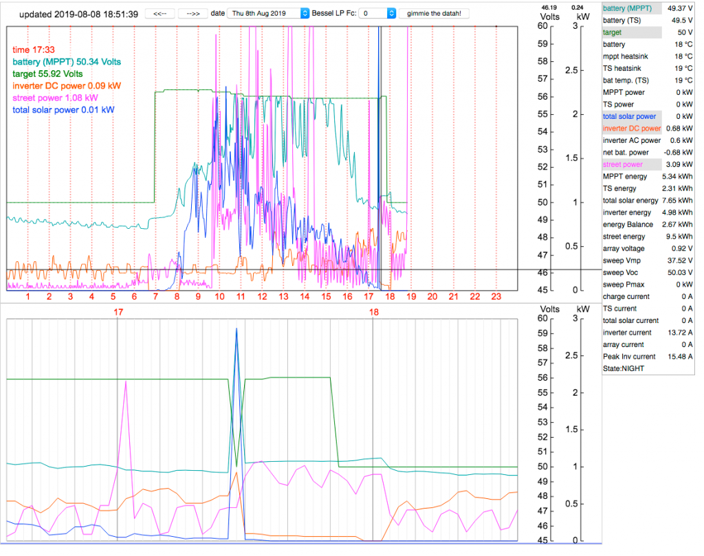 Looking at the lower graph you can see it puked and died at 17:30, and pulled a few amps. Of course, you need a few amps to make the magic smoke, and keep it coming. (my wife _adores_ the stench of what I like to call "scientific progress") I've altered my logging system web interface. I like it, now I have zoom into some time period. Maybe I need to just stick with software and....mutter,mutter.. wronger than a phone book full of wrong phone numbers |
||||
renewableMark Guru Joined: 09/12/2017 Location: AustraliaPosts: 1678 |
Why did the solar pulse so high at the same time? BTW I only run 5 fets in mine, no need to put in all 6, and my wife gives it hell.... still lives. Cheers Caveman Mark Off grid eastern Melb |
||||
| poida Guru Joined: 02/02/2017 Location: AustraliaPosts: 1392 |
usually it happens, it's an artifact or nonsense data. The mppt charge controller probably had a hiccup due to the high current incident when things went ka-pow. It might have reset or something. The main issue is I have about 10 hours of desoldering, rebuilding and testing ahead of me. And when that's done I have zero confidence it won't happen again. Need to make changes or else it's that old "do the same test and expect a different outcome" insanity. wronger than a phone book full of wrong phone numbers |
||||
| renewableMark Guru Joined: 09/12/2017 Location: AustraliaPosts: 1678 |
Don't desolder the fets, just work them back and forth to snap the legs. Then the remaining stubs of the legs will come out easy. Cheers Caveman Mark Off grid eastern Melb |
||||
| noneyabussiness Guru Joined: 31/07/2017 Location: AustraliaPosts: 506 |
Poida, just a bit of info if helpful, the 10kw powerjack i built years ago had a similar issue. On the bench with a small transformer it would preform beautifully, attaching it to the 90kg+ transformer it would last 2 hours or 2 days and explode. Very frustrating months... the transformer builder suggested that i put a small series resistance between ground and each mosfet, confusing them for npn transistors. But it did give me the idea to put a small resistance between the h-bridge output and the transformer, this case .1 ohm (mind you thats still a ton of heat to dissapate at 10kw) and it has lasted since... i did try all manner of inductors etc. But this worked.. Just food for thought. .. oh and i haven't forgot those beads, just housebound at the moment, had surgery thats failed and in a lot of pain... sorry its taken so long. . Edited 2019-08-09 07:36 by noneyabussiness I think it works !! |
||||
| johnmc Senior Member Joined: 21/01/2011 Location: AustraliaPosts: 282 |
Poida,Where are the spikes in your data being generated from, and how do you separate the street supply from the inverter output? I found that only connecting inverter to battery, then at the battery, all other inputs and outputs were taken only from the battery, but a small resistance was added by using a steel washer between the cable and battery connection. Do you need more HY 4008 fets ? Cheers john johnmc |
||||
| poida Guru Joined: 02/02/2017 Location: AustraliaPosts: 1392 |
The pink line (street power) has a lot of spikes. These are real. That day my wife used the slow cooker, and once it got to temp, it then cycled a bit of power regularly to maintain temp. Some very singular spikes are when she makes a cup of tea. This data is so accurate I can tell if we leave a 40W light on by mistake. I get the street power from counting 1 Watt.hr pulses coming from the power meter. This is quite noise immune. I put a photodiode over the LED on the Landis & Gyr meter, locate it with duct tape and close the meter box door. Cheap Cat 5 cable runs about 30M to the Arduino. The inverter power is from a current sensor on the DC input and the Morningstar mppt data I obtain via the modbus/web interface which contains the battery voltage. I presume I get about 90% efficiency and so need to scale it accordingly in my mind. Getting the inverter AC output current is a bit of a problem. What does the measurement mean? There is of course two AC power values, Real power and Reactive power. I can get the magnitude of the vector sum of the Real and Reactive power, by obtaining the product of the RMS voltage and RMS current. Getting the RMS voltage is easy and accurate, getting the current is harder thanks to huge noise everywhere if you use current sensors or transformers. The cheap Din rail modules that measure AC voltage and current are perfect for the job, and one is fitted to my spare home built inverter. Again I count the 1 Watt.hr pulses from that and get the AC output power. Some modules have pulse outputs for Real and Reactive, mine only has Real. here is the DC power and AC output power from last Sunday. The peak DC power is 0.95kW, the AC power from the module is 0.83kW just to the right of the vertical line. Near enough to 10% loss. There seems to be a constant offset on the DC power curve too and when that is removed things might look better. Around the time of 0.95kW I recorded peak DC current of 55A when a fridge started up. 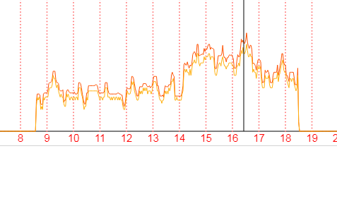 I only really care about the power drawn from the battery. The charge balance of the battery is my primary concern. Not sure what you mean by this. I have voltage sensing on the battery terminals. Always, every morning I eat a bowl for breakfast. I think I will get 6 from RenewableMark tomorrow to make up the 24 needed. I better order some more today. Thanks for the offer. wronger than a phone book full of wrong phone numbers |
||||
| poida Guru Joined: 02/02/2017 Location: AustraliaPosts: 1392 |
heh, I just had a look at peak current for yesterday. I recorded a peak of 93A at the time of failure. There is a 100A explosion proof fuse in line to the inverter supply. wronger than a phone book full of wrong phone numbers |
||||
| Solar Mike Guru Joined: 08/02/2015 Location: New ZealandPosts: 1129 |
As an experiment you could try using a higher rated current and voltage mosfet like the HY5110W available from LCSC, just in case a voltage spike is killing them, it only takes one to self destruct and the rest follow. HY4008 is only 80 volts, with the supply source on AliExpress suspect at best. Cheers Mike |
||||
| johnmc Senior Member Joined: 21/01/2011 Location: AustraliaPosts: 282 |
My battery connection consists of, 10mm 304 s/s bolt through the inverter 70mmx10mm cable lug ,then the battery post (cable lug face to battery post face) bolt through battery post then washer and nut tightened . The battery bolt is long enough, to then allow, the other battery connection, to be made,on the battery post opposite the inverter cable side. This consists of s/s washer cable lugs washer and tightening nut. My reasoning ,(correct or not) is that the increased resistance of the stainless steel bolt and washer tends to dampen the spikes and allow the battery to further absorb the spikes. An interesting side note, my 24v 4.5 kw commercial inverter has 120, "30 per quadrant" IRF 3205 specs 55v 110 amp fets and no heatsink, imagine the soldering joy. cheers john johnmc |
||||
| renewableMark Guru Joined: 09/12/2017 Location: AustraliaPosts: 1678 |
The FETS shouldn't be seeing big spikes in voltage. That voltage should be coming from the batteries. If the wiring from the solar is connected direct to the battery and not a bus bar away from the battery then the solar power shouldn't be spiking into the inverter. I was able to pick up spikes directly in the DC lines in the inverter that were from the solar before I fixed up the wiring. After that wiring got fixed all my problems went away and haven't done a repair since. Wife gives it hell and it only has 5 fets per 1/4 Thinking about it though, it's probably good insurance to use those 5110 fets . Edited 2019-08-09 16:40 by renewableMark Cheers Caveman Mark Off grid eastern Melb |
||||
| Solar Mike Guru Joined: 08/02/2015 Location: New ZealandPosts: 1129 |
Its when they turn off that the very short duration spikes can occur, some inverters will require a snubber network, some wont, depends on wiring and layout, all builds will be different in that respect. Cheers Mike |
||||
| poida Guru Joined: 02/02/2017 Location: AustraliaPosts: 1392 |
I just now ordered the last 32. Maybe use these in the next build, on a new PCB. wronger than a phone book full of wrong phone numbers |
||||
| Solar Mike Guru Joined: 08/02/2015 Location: New ZealandPosts: 1129 |
Good one poida, I was just going to order some of those for my PWM controller, no hurry though, still on pcb design. Cheers Mike |
||||
| BenandAmber Guru Joined: 16/02/2019 Location: United StatesPosts: 961 |
I don't know if this is good or not Was going to use a busbar but got scared when everybody warned me So did it like this What u guys think 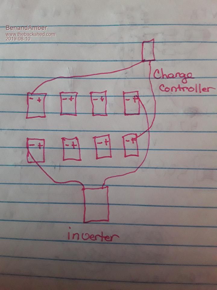 be warned i am good parrot but Dumber than a box of rocks |
||||
| poida Guru Joined: 02/02/2017 Location: AustraliaPosts: 1392 |
B & A I don't think it's going to fly, let alone blow up. Others here will help better than I can. wronger than a phone book full of wrong phone numbers |
||||
| poida Guru Joined: 02/02/2017 Location: AustraliaPosts: 1392 |
And it's time again for our most favourite type of post: Disaster P0rn. The low side MOSFETs were punished this time. They must have upset the Gods. 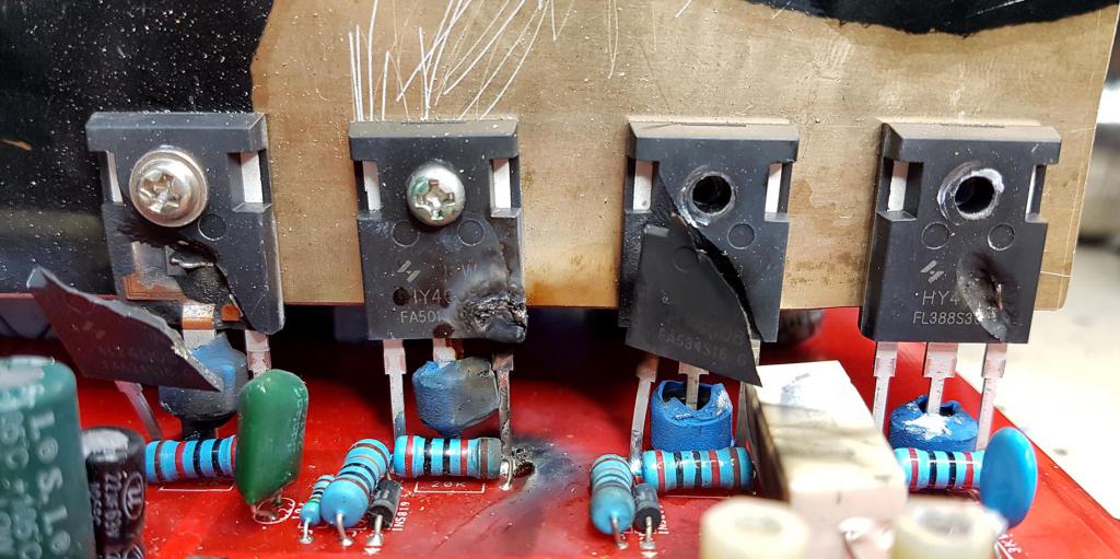 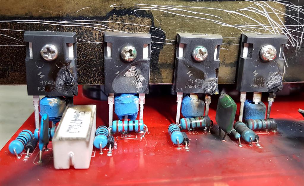 OF course the high side MOSFETS were blown too. They just stayed in one piece. The low side TIP41/42 pairs suffered. 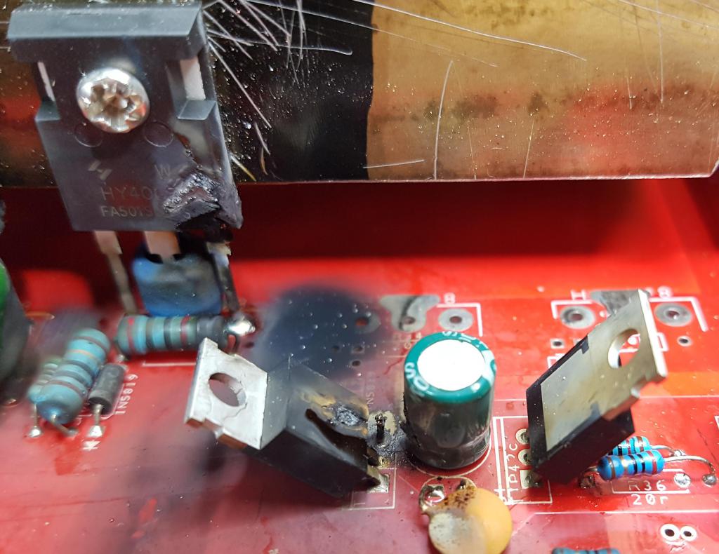 And the caps did not have a good day either. 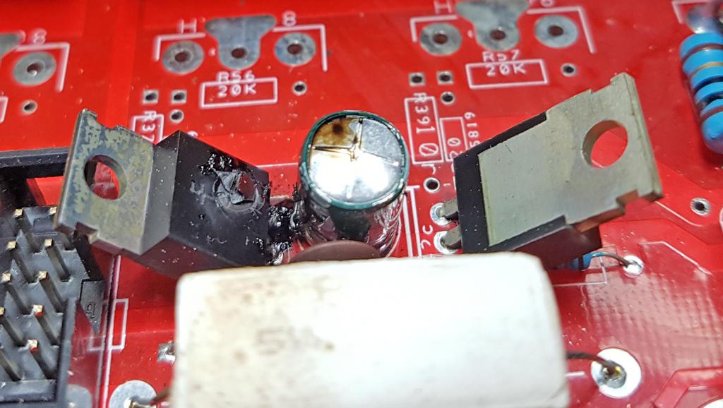 wronger than a phone book full of wrong phone numbers |
||||
| kentfielddude Regular Member Joined: 09/05/2019 Location: United StatesPosts: 89 |
maybe try using 1n4148 diodes. Madness uses the 1n4148s. Edited 2019-08-10 14:54 by kentfielddude |
||||
| renewableMark Guru Joined: 09/12/2017 Location: AustraliaPosts: 1678 |
I just noticed how much your fets overhang the heatsink. Any chance you're getting a hot spot on them causing them to go bang? Cheers Caveman Mark Off grid eastern Melb |
||||
