Notice. New forum software under development. It's going to miss a few functions and look a bit ugly for a while, but I'm working on it full time now as the old forum was too unstable. Couple days, all good. If you notice any issues, please contact me.
Revlac Guru Joined: 31/12/2016 Location: AustraliaPosts: 961
Posted: 01:47am 11 Sep 2017
Copy link to clipboard
Print this post
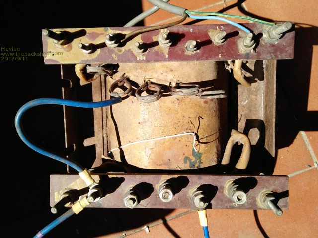
OK there has been a few inverters built using rewound toroids, quite impressive too. Its getting a little more difficult to find toroids as most new GTI's don't use them, at least not large ones anyway. There is some good size EI transformers around, if they could be put back to work doing something useful instead of tripping over the damn things or ending up waisted as scrap. The idea was to try and get an EI Transformer with enough grunt to run the power tools in the shed, It will mostly run during the day so Im not too bothered about the idle current or the efficiency, but will try and get an acceptable amount that I can be happy with. This is what I have found so far.
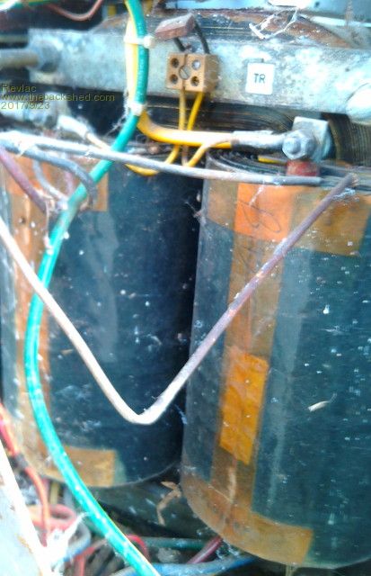
Transformer measured 1.06volts per turn buy running a small wire around the windings core is 70X80mm Weight 27KG Tested 50volts at the battery 235v on the AC side (driven by the EGS002 inverter) current draw no load @ 27 volts on the primaries: no choke .913amp 46 Watts on the 26 volt winding .850amp with the E core choke 5 turns .685amp 34 Watts now I did try the 25v winding and found a significant drop in the no load current, however there must be some point where running a low voltage through the primaries that its to low for the little EGS002 PWM to handle safely?
I have run various loads, water pump, small air con, large angle grinder, large fan and a freezer without a choke, the current draw (efficiency) was terrible. But I must say when running with a choke the results where looking pretty good for average loads, at least as good as the High frequency inverter that is running the house ATM.
Its was some time ago when I tested this and haven't done anymore with it after blowing up a few fets and the 002 board, have so much other work to catch up with, hope to get back onto it soon.
Will Try again with proper current meter.
As this is a multi tap transformer there is a few different voltages to play with and see what turns out better, there is also another tap 300volts I think from memory, If I use that tap it would lower the volts per turn? Is there any benefit in trying that? Or just keep the turns ratio the same as the toroids are wound?
I don't really want to rewind this one as its good to play with for a bit until I get something a little bigger.
Cheers AaronCheers Aaron Off The Grid
Revlac Guru Joined: 31/12/2016 Location: AustraliaPosts: 961
Posted: 02:39am 16 Sep 2017
Copy link to clipboard
Print this post
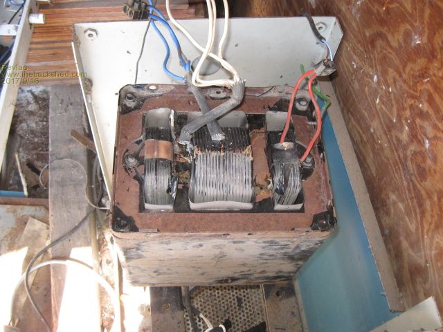
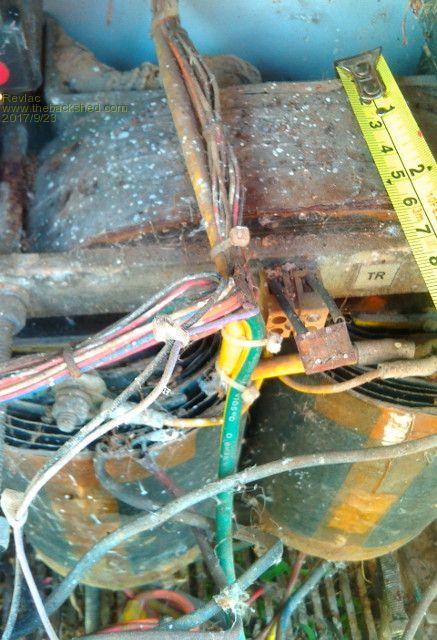
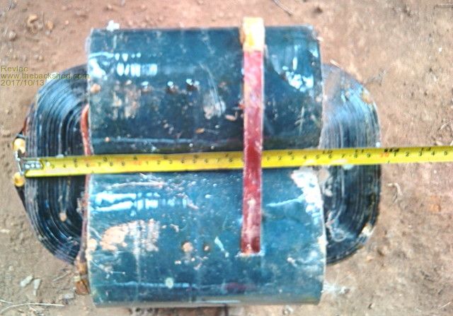
Now the next one is 200x50mm and a hefty 105Kg its from an old PSU for a computer system back in the 1980's probably even earlier. Has 240v to 110v step down and a capacitor filter was connected to the winding on the left side. The core is held in place with 2 bolts and would make rewinding the thing pretty easy If I decide to use it for an inverter.
Strange looking thing never seen anything like it before. Perhaps there is a good reason for that.
My 20 HY4008 Fets have arrived.
Cheers AaronCheers Aaron Off The Grid
Madness Guru Joined: 08/10/2011 Location: AustraliaPosts: 2498
Posted: 03:05am 16 Sep 2017
Copy link to clipboard
Print this post
Gidday Aaron,
That's a monster of a transformer, certainly would be easy to wind if the middle will come out. Do you mean 200 X 500? there is nothing in the photo to compare the size too. If it is no use for anything else you might as well rewind it, could you keep the 240V winding and just add your inverter primary?There are only 10 types of people in the world: those who understand binary, and those who don't.
oztules Guru Joined: 26/07/2007 Location: AustraliaPosts: 1686
Posted: 11:04am 16 Sep 2017
Copy link to clipboard
Print this post
Thats a high leakage transformer, and will need to be rewound differently to get decent performance out of it. It has sloppy coupling, and with shunts as well, looks more like a battery charger configuration to me.
If you rewind with the secondary spread out on the core from end to end, and wind the primary over that , your coupling will be much much better.. we want tight coupling for this purpose.
As it is wound presently, leakage will be a big worry. It will mean you will drive much higher peak currents for no gain when under higher power... would no try to go much over a kw or so in it's present guise.
When wound tightly, it will be very good, but with idle current about twice the losses of a torroid would be my best guess
.........oztulesEdited by oztules 2017-09-17Village idiot...or... just another hack out of his depth
Revlac Guru Joined: 31/12/2016 Location: AustraliaPosts: 961
Posted: 04:27am 17 Sep 2017
Copy link to clipboard
Print this post
G'Day Mad I don't think I would have any use for it as a step down transformer anymore, will plug the power meter into it with 240Vac and check a few things before I pull it apart. Then investigate further This one is rated at 3.5Kva
Hi Oz I can cut the size down if I need to and there is some other parts in there that may need to be cut out also to achieve a good winding over the full length, will do another photo when I take it apart. some good copper wire in it too I'm happy with the first transformer pictured, It must be wound properly
I still have some other contenders will post them soon
Cheers Aaron Cheers Aaron Off The Grid
joebog1 Senior Member Joined: 07/11/2015 Location: AustraliaPosts: 114
Posted: 02:32pm 17 Sep 2017
Copy link to clipboard
Print this post
I would suggest that the big traffo is a constant voltage transformer!! They were extensively used in early UPS's. It is best suited to a boat anchor as far as an efficient inverter goes. I have seen them before and it looks like a "Deltec" inverter transformer. When the mains was up, it worked as a battery charger, when the mains failed a BIG contactor changed it over to an inverter. Its late 60's early seventies stuff.
Hope that helps. Joe
p.s. I chucked a few of them away!!!
Its also known as a ferro resonant transformer. when they work hard they make more noise than a diesel generator.
Some further thinking on that transformer!! It was driven by huge SCR's that are about 3 inches/75 mm long and one inch/25mm square. one SCR and one cycling diode per package. They were made by Seimans.Edited by joebog1 2017-09-19
Revlac Guru Joined: 31/12/2016 Location: AustraliaPosts: 961
Posted: 03:46am 19 Sep 2017
Copy link to clipboard
Print this post
Hi Joe Well I think you have almost nailed it. Its labeled as Sola Electric Computer Regulator, but it appears to be as you described.
I was scratching my head for a bit over the SCR part you mentioned Then I realize that I striped apart a unit a bit like that some time ago,(Plugged into the transformer somehow I think) had a load of capacitors, power transistors, thyristor's, SCR's,diodes control boards etc. The best or most useful part so fare would be the single and double stack ferrite cores it had.
There I have learned something new. Or is it something old.
Will post some other transformers on the weekend when I have time.
Cheers Aaron Cheers Aaron Off The Grid
oztules Guru Joined: 26/07/2007 Location: AustraliaPosts: 1686
Posted: 11:03am 19 Sep 2017
Copy link to clipboard
Print this post
Aron, the ferro resonant tranny still has good laminate in it, and so is not throw away. Can certainly be used if rewound.
Those transformers run in saturation, and thats part of how they self regulate... ie a change in line voltage will have little effect on the core magnetization, as it is saturated anyway.....masks the line noise as well, thats why they are inefficient at low loads....but if you drop the primary input ac voltage, knock out the chokes, it can be used as a normal tranny... if you don't lower the input ac, then it will saturate more than when you had the controller inside.
At full loads, they can be as high as 92% efficient, but at low power, they may be as low as 20% efficient and less. As a charger generally in the 50-75% range overall, as full power is mostly of short duration, before it settles in to the bulk charge... which will be well less than 100%, so efficiency suffers dramatically.
It seems to be an American thing. I never saw a Aust traction charger using this kind of tranny, but a plethora of American ones did.
........oztules
Village idiot...or... just another hack out of his depth
joebog1 Senior Member Joined: 07/11/2015 Location: AustraliaPosts: 114
Posted: 01:58pm 19 Sep 2017
Copy link to clipboard
Print this post
A thing to check before you try and undo that transformer!! Check to see if there is a gap in the "middle leg" ( stop larfing!! ) Deltec and Solar Basic is same company!! you will probably find its hi-potted. Read: lots of beer lots of patienec and be prepared to lose some laminations, the proverbial PITA to undo.
Gday oztules, there were constant voltage transformers made in Aus. Most by Ferguson Transformers. They were almost exclusively ( MY experience) used in recording studios mostly to run Scully lathes. Shheze thats a long time ago
Joe
Revlac Guru Joined: 31/12/2016 Location: AustraliaPosts: 961
Posted: 04:33am 20 Sep 2017
Copy link to clipboard
Print this post
Gday oztules
I will certainly have a play with it (the transformer I mean:) will know more when I take it apart There is also a few ex Telecom 48v battery charges here, one of them I use to charge the lithium battery bank. Runs well too, will take a look at them next.
Gday Joe
Yep the middle leg has an air gap at the end about 3/16th the other end is tight
I'm only about half the age of both of you, and still find it hard to keep up with the new tech. but I will get there eventually
Cheers Aaron Cheers Aaron Off The Grid
Warpspeed Guru Joined: 09/08/2007 Location: AustraliaPosts: 4406
Posted: 07:58am 20 Sep 2017
Copy link to clipboard
Print this post
Cheers, ĀTony.
Warpspeed Guru Joined: 09/08/2007 Location: AustraliaPosts: 4406
Posted: 08:22am 20 Sep 2017
Copy link to clipboard
Print this post
Ah yes, I was once a power electronics design engineer at Sola in Melbourne. Old man Sola held all the original patents on ferroresonant transformers.
One of my creations while there, was a UPS which used a ferro with two primary windings. One winding was driven by the 230v mains, and this provided normal straight through power with excellent voltage regulation and noise suppression.
On mains failure, a second lower voltage primary was driven by a 50Hz push pull square wave inverter run from a battery.
The amazing thing about ferro transformers is that they create a clean voltage regulated sine wave output, even when driven by a square wave of varying voltage on the primary. So as the battery voltage gradually falls, the 230v output still drops slightly, but not by very much. Thirty percent drop in battery voltage might only produce about a three percent drop in sinewave output voltage.
Another interesting feature is that when the incoming mains fails, a ferro will keep going all by itself for a cycle or two, well enough to start up the inverter without having any interruption to the output. It all makes for a very simple and bullet proof UPS.
These used to use either big darlington transistor blocks or sometimes cross commutated SCRs in the inverter. Today the inverter switching would all be done much more efficiently with mosfets.
If you want a big reliable sine wave inverter, and don't care too much about size, weight or efficiency, a big ferro (especially if its free) might make an interesting thing to play with.Cheers, ĀTony.
Revlac Guru Joined: 31/12/2016 Location: AustraliaPosts: 961
Posted: 03:28am 23 Sep 2017
Copy link to clipboard
Print this post
HI Warpspeed I see you have no problem designing and building your own gear. The changeover speed on some small ups these days (cheep 500w version I had) is not fast enough for some equipment, At 10ms transfer time, my old computer used to drop out. Some local shopping centers don't have a backup geny or UPS, the grid went down and they just shut the door. A few have industrial size UPS (Think the inverter transformer runs full time) Keeps the cash registers going.
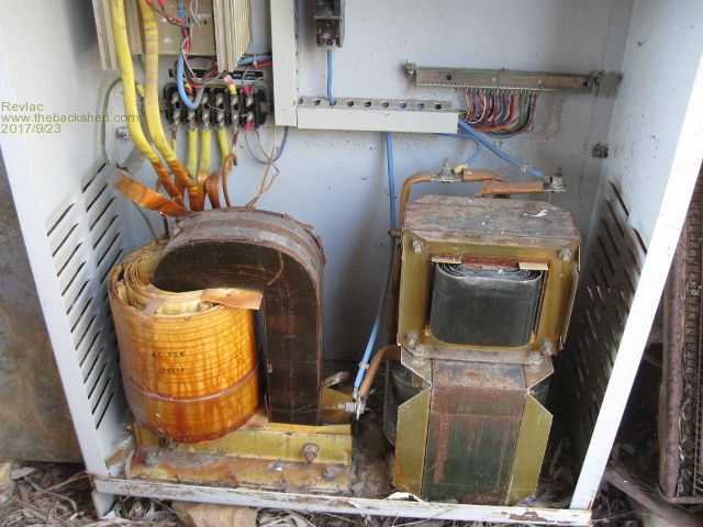
These battery chargers used by Telecom were built strong and could connect up to 100 of them together if they had the communication wires connected.
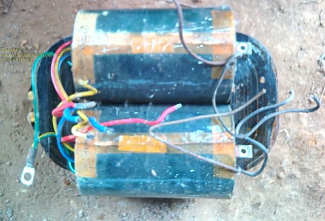
This one is Power Electronics charges about 50A, Have run it to 60A no problem provided I don't mess around with the current limiter, (Snaps the breakers off almost instantly) it uses a block SCR and Diode configuration very robust design IMO. Have one identical to this, charges the lithium battery bank sometimes, noisy 80 decibels @ 1m.
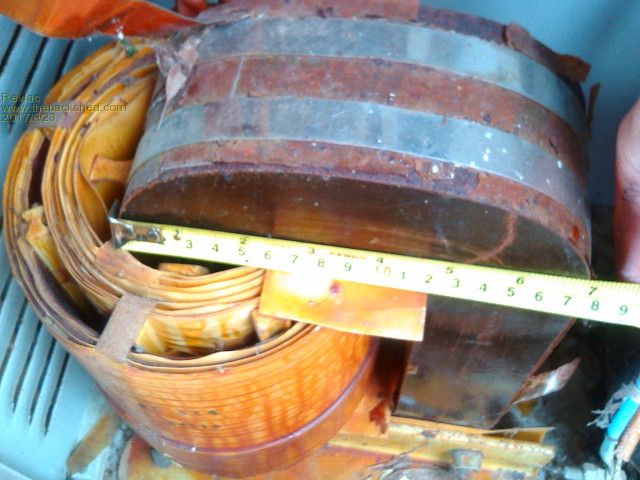
The 2 different size chokes are huge. The transformer looks like 2 horse shoes strapped together output is 80v.
Would be quite a large area to rewind a new secondary and primary on to it. Has a large air gap between the primary and secondary ATM
This next one Is L.M.Ericson much the same but more compact
pictures are a bit crappy from the phone camera. Batteries in the good camera leaked and stuffed the inside of it.
Has smaller core area but they covered more of it. I think theses core's may be worthy contenders.
Also have a transformer from a CIG 150 mig welder my only dislike about that one is all the laminates are welded together where as all others I have are bolted (clamped together)
Well Them's my choices
Cheers Aaron
Cheers Aaron Off The Grid
Madness Guru Joined: 08/10/2011 Location: AustraliaPosts: 2498
Posted: 10:57am 23 Sep 2017
Copy link to clipboard
Print this post
A few years ago I rewound a burnt out 240A MIG welder transformer. Took two of us a couple days walking every turn through the core, should have paid the $280 for a new one.There are only 10 types of people in the world: those who understand binary, and those who don't.
Revlac Guru Joined: 31/12/2016 Location: AustraliaPosts: 961
Posted: 03:15am 24 Sep 2017
Copy link to clipboard
Print this post
Your lucky it wasn't 3phase , would be a real PITA I ended up buying a complete 180amp 3phase mig welder from an auction $50 just needed a new 10A bridge rectifier, found a few in the shed, had it up running within 20 minutes of getting it home.
So handy just put something together from junk that some of us manage to find and collect
After reading Warpspeed's post on the other thread I would say these battery charges are C-Core type transformers.
Cheers AaronCheers Aaron Off The Grid
Revlac Guru Joined: 31/12/2016 Location: AustraliaPosts: 961
Posted: 03:10am 13 Oct 2017
Copy link to clipboard
Print this post
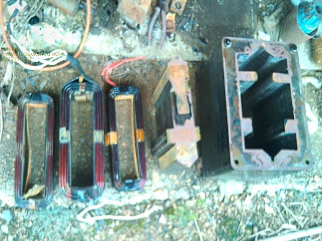
Finally managed to get that Big Transformer apart, thought it would be an easy job, just take the bolts out then slide the center out, But no! after stuffing around trying to press it apart with a jack, the middle leg would not move, stuck in tight with paint. I ended up separating all the laminates just to free it up. Anyway this is how it turned out, looks like a bit more work than I have time for ATM.
Core is 100cmsq Volts per turn was 3.7 primary was 64 turns About 1.5 Tesla
This is the calculations That I thought would be appropriate For 48Volt by 235Volt primary turns 14 Secondary turns 127 Tesla 0.833 Turns Ratio 9:1
This might have to go on the back burner for a bit.
I have this C core that should be a little easier start with. For low idle current I'm looking at 0.575 volts per turn. Core is 52x60mm primary turns would be 45 secondary turns 405 Tesla .837 Again that is a 9:1 turns ratio, might work it down to 8:1 yet
Just depends on how that many turns will fit with the size of wire that I have.
Thank's Warpspeed for the link to that Tesla calculator, Had fun with that.
The little EI Transformer I started with on the first page is also 9:1 ratio and .8 Tesla.
Cheers Aaron Cheers Aaron Off The Grid
azhaque Senior Member Joined: 21/02/2017 Location: PakistanPosts: 117
Posted: 05:04pm 11 Nov 2017
Copy link to clipboard
Print this post
Hi Guys, Writing from Islamabad Pakistan.
Toroidal cores being unavailable here I am going to get an 5 KVA E-I type transformer wound, for the under mentioned Chinese inverter board based on 8010 chip.
My question is how do I calculate the turns ratio and the other transformer parameters for this SPWM inverter board so that I can come up with the most cost effective and efficient design.
Links to any article on the Net are highly appreciated.
By the way the inverter is to run my off grid home that is nearing completion.
Regards
A. Haque
Warpspeed Guru Joined: 09/08/2007 Location: AustraliaPosts: 4406
Posted: 03:15am 12 Nov 2017
Copy link to clipboard
Print this post
[quote]I am going to get an 5 KVA E-I type transformer wound[/quote]
In that case, you let the transformer man design the transformer, and then just pay.
He will design it, as it will be something he does every day, and unless you know a lot more more about it than he does, best let him do all the design work.
If you are going to do this all yourself, first find a suitable 5Kva transformer of some type to rewind. Perhaps out of a large welder or very large fork lift battery charger.
I strongly suggest you start off with a smaller transformer to experiment with and test. Get that all sorted out before you begin rewinding the monster. Cheers, ĀTony.
Warpspeed Guru Joined: 09/08/2007 Location: AustraliaPosts: 4406
Posted: 03:44am 12 Nov 2017
Copy link to clipboard
Print this post
Aaron,
Either of those C core transformers look promising, provided you can separate the two halves. They will almost certainly be dipped in transformer varnish and then oven baked.
That effectively "glues" the whole thing into one solid lump, and sometimes they come apart fairly readily and sometimes they don't. It may take something like a very large chain block, a sturdy metal frame, and several tons of force, but see how you go. Don't be too surprised if you cannot get them to come apart.
The ferroresonant transformer is completely useless for anything other than a ferroresonant transformer. Its junk.Cheers, ĀTony.
azhaque Senior Member Joined: 21/02/2017 Location: PakistanPosts: 117
Posted: 06:00am 12 Nov 2017
Copy link to clipboard
Print this post
Thanks for the tip WARPSPEED.
How I wish that could happen. In Pakistan the people in the market providing transformer winding services are just copycats. I just spoke to one who asked me if I had a piece that he could copy. Now I am trying to figure out what to do. Even if I start with a 1 KW unit- which I believe is sound advice, what turns/volt do I use. What should be the flux density to use, etc. etc. are questions that these guys would have no answer to. So here I am...