
|
|
Forum Index : Microcontroller and PC projects : The Micromite needs a (p)HAT
| Page 1 of 2 |
|||||
| Author | Message | ||||
| matherp Guru Joined: 11/12/2012 Location: United KingdomPosts: 11512 |
The Raspberry Pi community don't seem to do "soldering" but this has resulted in the development of a HAT culture with numbers of interesting sensors mounted on small PCBs that mount onto the Pi 40-pin connector. Typically these are much cheaper and have more functionality than mikro-BUS modules and are much easier to connect to a Pi than the typical individual breakout modules. A typical example is the Pimoroni Enviro pHAT but there are large numbers of different "HATs" now available so why not use them with the MM? I feel a PCB design coming on  The 28-pin Micromite has 19 I/O pins (not counting the console) whereas the Pi has 26, but rather than use one of the bigger Micromites I did a detailed analysis of a large range of HATs and developed a pin mapping between the MM and the Pi that caters for all the ones I checked. The constraints were to ensure that the key HW functionality was properly mapped (COM1, I2C, SPI, PWM) but at the same time try and ensure that all the various other I/O on the HATs could be catered for by the MM. The attached spreadsheet was my tool for doing this and it includes 18 different HATs that can all be connected properly. Column AL in the spreadsheet can be used to test any other HAT for compatibility. Just put a 1 in the cells corresponding to the Pi pins needed for the HAT and as long as none of the mappings are duplicated they will be displayed normally in column AM. In case of duplication they will be displayed with a pink background as in the example "User pHAT. 2017-09-28_113840_pHAT.zip Having got a useful looking mapping I've then laid out a MM PCB. This uses the normal DIP PIC32MX170 and a DIP PIC16F1454 as the Microbridge/MX programmer. The challenge was to do this on a PCB the same size as the Pi Zero (65x30mm) but keep soldering as easy as possible. 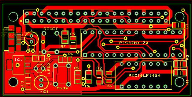 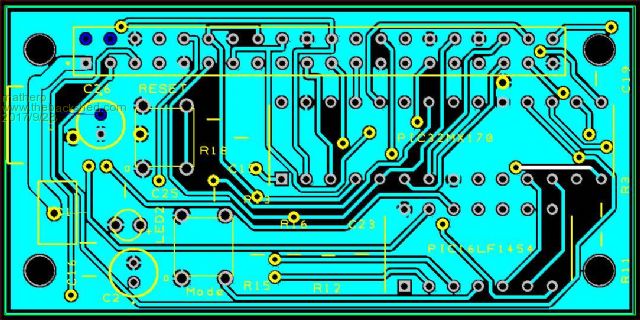 2017-09-28_143852_schematic.pdf There is only one tricky component to solder - the USB connector. Otherwise the SMD parts are the regulator and 1206 size resistors and capacitors, all as easy as through-hole parts. I haven't ordered any PCBs yet so feedback on the idea and any errors would be appreciated. As always I will make the gerbers available once I'm happy with them and you know the people who need arm-twisting if you want bare PCBs or completed boards. |
||||
| MicroBlocks Guru Joined: 12/05/2012 Location: ThailandPosts: 2209 |
It is very close to being all through-hole. I think you'll make a lot of people happy when it is completely through hole. Maybe only the vcap has to stay smd, but even a 47u tantalum through hole version will i think probably fit. Are the push buttons easy to reach when it is in use? Maybe to make a bit more room you can replace them with pins? Microblocks. Build with logic. |
||||
| led-bloon Senior Member Joined: 21/12/2014 Location: AustraliaPosts: 209 |
A great idea.  The only prerequisite for interfacing to the RaspberryPi hats is the 40 pin connector and its functionality. Does the size of the PCB need to be so small? Would an added connection to "click" boards extend functionality? At least diversity of supply. I too would like to see through-hole components used throughout, also both buttons moved to the edge of the pcb for right-angle mount buttons to be used. Irrespective, great work & thanks. led Miss you George |
||||
| astro1 Regular Member Joined: 26/06/2016 Location: AustraliaPosts: 53 |
How about a jumper (maybe a solder bridge type) for +5v from the USB connector to the 3v3 reg. Add 1 extra pad for a gnd, to hook up external 5v? |
||||
| matherp Guru Joined: 11/12/2012 Location: United KingdomPosts: 11512 |
Thanks for the feedback: Micro USB is now ubiquitous for powering pretty much all devices so I don't see the need for another connector - you don't need to use it for USB connectivity just power if program is set to AUTORUN The microUSB has to be surface mount and is the only vaguely tricky thing to solder. 1206 parts really are just as easy as through hole once the fear-factor is overcome. In any case through hole isn't doable on the PCB this size as the leads would compromise routing on the bottom of the PCB too much . I've moved the reset to board edge. Any HAT must be removed before using the mode switch otherwise PGD/PGC may be compromised so that one shouldn't be an issue No - but a bigger one with more connectivity would be a different concept, perfectly valid but different - the idea of this board was to match the size of the Pi-Zero and many of the HATs 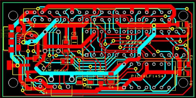 |
||||
Grogster Admin Group Joined: 31/12/2012 Location: New ZealandPosts: 9975 |
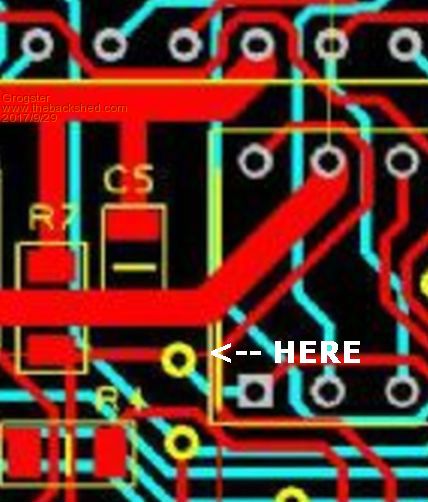
[Quote=matherp]1206 parts really are just as easy as through hole once the fear-factor is overcome.[/Quote] TOTALLY agree with that, and I speak as someone who was so scared of SMD five or six years ago, that even SOIC with it's relatively huge 1.27mm was too small for me.  SOT-23 was out also - too tricky to solder - or so I thought at the time. Now I have got used to it, most things I design are SMD down to 0.6mm SSOP chips or the MM+ series at 0.5mm - no problem to solder these now, and I can just about do them in my sleep.  I know many still fear the SMD thing, but you just can't do some things as through-hole, and speaking as someone who was frightened to death of SMD and small pin-pitch parts, it really was the best thing to happen to me - losing my fear of SMD, cos it opens up an entire world full of different choices in various devices that simply are not manufactured in DIL or through-hole flavour. Assuming I am looking at Peter's layout correctly, is not pin-1(MCLR) connected directly to pin-28? I have always pulled MCLR high with a 10k, but never directly connected MCLR to any other pins....  Smoke makes things work. When the smoke gets out, it stops! |
||||
| matherp Guru Joined: 11/12/2012 Location: United KingdomPosts: 11512 |
Certainly shouldn't be and I don't think it is but you may be seeing something I'm not so please let me know where you think the issue is - thanks |
||||
| Grogster Admin Group Joined: 31/12/2012 Location: New ZealandPosts: 9975 |
 Smoke makes things work. When the smoke gets out, it stops! |
||||
| matherp Guru Joined: 11/12/2012 Location: United KingdomPosts: 11512 |
Ah - I see the reason for confusion. The thin red line you have identified is the logical edge of the copper pour area and not a track. When I pour the copper it won't fill where there are other tracks. The actual track from pin 28 goes vertically down behind the silkscreen and then turns right under pin 1. You can also see the edge of the pour area centre bottom of your image. Phew... |
||||
bigmik Guru Joined: 20/06/2011 Location: AustraliaPosts: 2981 |
GDay Peter, My only thought is that the mounting holes don't have sufficient clearance from nearby tracks/pads.. Not an issue if a nylon or fibre washer is used under the mounting nut and metal standoffs (if metal is used). I would suggest totally using Nylon in any case. Now a question, What would you do with it? Unless it is to gain more I/O? Kind Regards, Mick Mick's uMite Stuff can be found >>> HERE (Kindly hosted by Dontronics) <<< |
||||
geraldfryjr Regular Member Joined: 02/03/2014 Location: United StatesPosts: 61 |
Cool Stuff !! I have a Chipkit Pi that I have been using, Basically very similar. jer  Keep on DIYin' !!!  |
||||
| Intellecta Newbie Joined: 07/05/2016 Location: AustraliaPosts: 22 |
Dear Peter, Great concept but I have an issue with: There is only one tricky component to solder - the USB connector More likely - impossible to solder. The micro usb pads are very small and usually under the body of the connector. I have used these components but have made the pads longer so that they are outside the body and you can apply some heat to the pad. Solder then flows onto the actual pin of the component. The component that you have chosen is fastened to the actual PCB by four small top surface copper pads. These are easy to tear off and then the board is useless. Maybe consider a mini USB connector with smd pads but 4 retaining pins that can be soldered on the top and bottom side. Thanks Tony Pugatschew |
||||
| matherp Guru Joined: 11/12/2012 Location: United KingdomPosts: 11512 |
Not at all, it is my standard microUSB part, and I hand solder it easily - see it is use here Just needs a fine tip soldering iron. I haven't included it in the design yet but the final layout will have vias in the pads through to the ground plane on the bottom. These anchor the connector and makes it difficult to damage. This connector also has 6 pads so it really needs some force to damage the board. I haven't managed it yet with any of the ones I have used it on. I do accept this can be an issue with micro-USB but the connectors are much better specified than mini in terms of number of insertions and power handling |
||||
| MicroBlocks Guru Joined: 12/05/2012 Location: ThailandPosts: 2209 |
In my experience the micro-USB on any device i (and my wife and kids) have had (phones, chargers, tablets etc) fail, while my older devices with a mini-usb are still perfectly fine. They were not silly chinese knock-offs either but Samsung, Nokia, Asus etc. Somehow the 'better' specification did not make it into the market. Another weak point is that when they are not soldered 100% and if the pads are not big enough and if the padfs do not have good enough adhesion to the pcb they will just tear off. And just to mention another weak point, when people try to connect the cable with the connector flipped it is another failure point. A mini-usb is also more resilient with that. The only advantage of a micro-usb smd version is that when you need to manufacture many products. Then it can be placed by pick&place machines and reflowed in the same process as all the other components. For the rest it is just a nuisance. Microblocks. Build with logic. |
||||
| robert.rozee Guru Joined: 31/12/2012 Location: New ZealandPosts: 2528 |
i really don't like micro-USB myself either, i rate them alongside micro SD-cards as a step-too-far. one thing worth consideration is these: http://www.ebay.com/itm/221890510788 and these: http://www.ebay.com/itm/191693039040 it would be relatively simple to design a PCB to accommodate either carrier board, so the hobbyist could then make their own decision between micro and mini USB. and if the USB connector does get damaged, it is pretty easy to replace the carrier board. i've used the mini-USB carrier boards myself, they are extremely easy to handle. the only fault i could raise is that the two front PTHs are not on the same 0.1" grid as the 5 signal ones. cheers, rob :-) |
||||
| Grogster Admin Group Joined: 31/12/2012 Location: New ZealandPosts: 9975 |
All this micro-USB socket hate.... The trick to preventing the tearing off of the micro-USB socket, is simply not to tug on the USB cable. I do acknowledge that a suitable tug on the USB cable at right-angles to the socket could and would(and does!) rip the socket off the board, but again - the trick to avoiding that, is to avoid that.  As to soldering the micro-USB sockets, I also have to agree with Peter, and say that they have always been easy for me to solder. As with the 0.5mm pin-pitch parts, you only use a tiny amount of solder, and flux. With flux and not too much solder, you can solder the pins on the micro-USB socket quite easily, really. Having said that, I can certainly appreciate and understand how many don't like them for that aspect alone, and don't like to solder them either. As with anything else in this world, practise makes perfect. Having said that - and that - I tend to opt for Mini-USB in all my boards if possible, and will only use micro-USB if space simply won't allow for a mini-USB socket. Smoke makes things work. When the smoke gets out, it stops! |
||||
| CaptainBoing Guru Joined: 07/09/2016 Location: United KingdomPosts: 2171 |
my 2p I don't like USB plugs/sockets for long term un/plugging, they all seem to get a bit "ragged" after a while - maybe the type B is the best from my experience.. I use 3.5mm stereo jack plugs where I can (not on the actual USB but on the serial side - Tx, Rx & Gnd) - very robust and if they are getting a good deal of use they tend to hang in the fight longer. I use them for console connections on a lot of my stuff, with a little socket mounted rubber stopper. looks neat, cheap as chips and really easy to work with, if a tad un-conventional. Not saying we should all be doing it, just another angle on the same problem everyone seems to have with USB sockets. |
||||
| WhiteWizzard Guru Joined: 05/04/2013 Location: United KingdomPosts: 2991 |
Ok - my turn! For a person soldering these SMD USB sockets (whether mini or micro), there is a 'fear factor' IF they are only used to soldering through-hole components. This is fully understood and I think we all agree. However, regarding USB sockets tearing off PCBs (again, whether mini or micro), then this is not a situation to worry about these days UNLESS you are very heavy handed. Sure, they fail in phones where they may be inserted/removed multiple times a day/week. But for a PCB/Module that Peter is proposing it is 100% fine. Micro USB did indeed use to be weaker than mini when the micro USBs first appeared. However, manufactures listened, and strengthen their designs. FACT - there are millions of RPis out there, and failure of micro USB sockets is not an issue (unless people have physically stressed them). So are people concerned about assembly, or about strength of socket? As Peter has said, they are robust, and solderable - just don't try using a welding machine to solder them and you'll be fine EDIT - Forgot to mention - Micro is the preferred choice for all things RPi - the PSUs are cheap, reliable, and easily available . . . WW |
||||
| astroboy Regular Member Joined: 28/12/2014 Location: AustraliaPosts: 41 |
Hi Now a question, What would you do with it? Unless it is to gain more I/O? Thanks Mick. I also wonder about this but was too afraid to ask for fear of showing my ignorance. Regards John |
||||
| WhiteWizzard Guru Joined: 05/04/2013 Location: United KingdomPosts: 2991 |
Due to the popularity of the RPi, there are literally hundreds of add-on modules for it. A 'standardisation' of sorts was agreed upon with the appearance of the 26way and 40way headers on the various RPi models (the 26way is a 'short version' of the 40way - i.e. a 26way module will work on a 40way RPi). So then HATs came along with typically the 40 way connector on them (plus some other RPi specific hardware such as an EEPROM containing info about the HAT). The idea of this module Peter has kindly put together is to allow the use of many HATs from a MMBASIC environment. HATs are reasonably cheap and therefore allow you to get something up and running quickly without worrying about needing to 'design or build' the hardware. So adding Gesture control to a MicroMite is now easy and cheap, as is indeed a Piano, or drum machine, or robot, or Environment Sensor, or Speech, or LED matrix, or LiPo Power Pack, or . . . . the list goes on and on. And lets not forget there are many RPi Zero cases to choose from (especially if Peter could move the micro USB power connector!  ) )Hope this helps you understand the idea behind this format of module . . . . WW |
||||
| Page 1 of 2 |
|||||
| The Back Shed's forum code is written, and hosted, in Australia. | © JAQ Software 2026 |
