
|
|
Forum Index : Microcontroller and PC projects : Sleeping and waking an HC12...
| Page 1 of 2 |
|||||
| Author | Message | ||||
Grogster Admin Group Joined: 31/12/2012 Location: New ZealandPosts: 9975 |
Hi folks.  I have finally been able to test this concept, and play around with various timings and commands, and the following code works well to sleep and wake HC12 modules, if you assign an I/O pin to the SET pin on the HC12 module. SUB HC12_SLEEP Pin(HC12)=0 'Enable setting mode on HC12 module Pause 25 'Allow HC12 to respond Open "COM1:1200" As #1 'HC12 module COM port - must use set baud-rate! Print #1,"AT+SLEEP" 'Put HC12 module to sleep Do:Loop Until Loc(#1) 'Wait for HC12 to respond Pause 100 'Allow all of response to arrive D$=Input$(Loc(#1),#1) 'Suck HC12 response from buffer Close #1 'You know what this does.... ;) Pin(HC12)=1 'Return to 'Normal' mode - this is when the sleep occurs Print "HC12: ";D$ 'Debug information End SUB SUB HC12_WAKE Pin(HC12)=0 'Enable setting mode on HC12 module Pause 25 'Allow HC12 to respond Pin(HC12)=1 'Return to 'Normal' mode Pause 250 'HC12 needs at least 200ms to re-initalize End SUB Might be helpful for those wanting to sleep their HC12's. Both SUB's are commented, so you should be able to see what each line is there for. One thing I did note, was that once you have programmed the HC12 with the likes of Rob's utility, when you enter command mode by pulling SET low, you have to talk to the module in the baud-rate as set. I thought this defaulted to 9600 baud for command mode as soon as you pulled SET low regardless of what baud-rate you had set, but this does not seem to be the case. I could only get a response out of the module at the set baud-rate, and nothing by gibberish at 9600 baud. I have been sleeping the HC12 up until now with an I/O pin and the NPN+MOSFET trick to switch the Vcc line to the module off and on. This software-sleep method allows me to sleep the module and NOT have to install four SMD parts.  Smoke makes things work. When the smoke gets out, it stops! |
||||
| CaptainBoing Guru Joined: 07/09/2016 Location: United KingdomPosts: 2171 |
you are the hc12 master! I have never played with the config pin or sleep (never used hc12 in battery/low-power application - yet) but it is good to note your finding re the different speed, thanks. I dare say that would have had me scratching the swede for a while |
||||
disco4now Guru Joined: 18/12/2014 Location: AustraliaPosts: 1127 |
I think Rob's version of the data sheets says that it will default to 9600 if set is held low when power is applied, but as you discovered remains as is if pulled low after power is on. Gerry F4 H7FotSF4xGT |
||||
| Grogster Admin Group Joined: 31/12/2012 Location: New ZealandPosts: 9975 |
Ahhhhhh - cheers, Gerry.  I knew I read that somewhere, but thought it was if you just grounded the SET line. Smoke makes things work. When the smoke gets out, it stops! |
||||
GoodToGo! Senior Member Joined: 23/04/2017 Location: AustraliaPosts: 188 |
Nice work once again Grogster! GTG!  ...... Don't worry mate, it'll be GoodToGo! |
||||
| lizby Guru Joined: 17/05/2016 Location: United StatesPosts: 3782 |
Thanks for this. Can you provide the HC12 configuration settings you use, so all will be in one place? PicoMite, Armmite F4, SensorKits, MMBasic Hardware, Games, etc. on FOTS |
||||
| Andrew_G Guru Joined: 18/10/2016 Location: AustraliaPosts: 883 |
Grogster, well done. If you recall this thread I was grappling with the same issue (with limited success). I haven't yet been able to measure the currents, sleep vs awake, that HankR was suggesting (around pages 3&4 of the thread). Without being too much of a pain?: - could you possibly measure and report them here so I can check my (eventual) readings? - also, could you possibly share a schematic of your circuit - I'm particularly interested in your use of a transistor to sever the line during sleep. Is the saving offset by any power required to drive the transistor? One thing I did notice with the setup is that both the send and receive units need to be in the same mode (eg FU 1, 2, 3 or 4) - it is not good enough to have them at the same baud rate but in different modes (I was trying to have the externally powered base station at a high power mode while the battery powered remote unit was in the lowest power mode possible). I use FU2 mode at 2400 baud (set by using Rob R's beaut config program). Cheers, Andrew |
||||
| Grogster Admin Group Joined: 31/12/2012 Location: New ZealandPosts: 9975 |
@ lizby - I just used Rob's wonderful HC12 CONFIG utility. 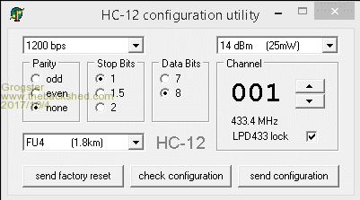 Rob's HC12 Utility @ Andrew_G - Yes, I measured the sleeping current. This was to be sure the module was indeed sleeping. My test was nothing more then a multimeter in series with the project that had the test HC12 on it. Current consumption with everything running including the HC12 was 44.9mA, when you sleep the HC12, the current drops back to 30.1mA, a difference of 14.8mA. Therefore, the current saving by sleeping the HC12 is around 15mA, which is a significant saving if you are running on batteries.The NPN+MOSFET idea is NOT mine, I stole it from the web and also other members here I think pointed me to this idea way back when. Here is an image of the same circuit I stole from Google Images: 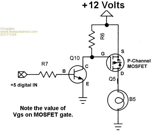 This was what I have been using up until now, but it requires four extra SMD parts. It is a high-side switch for just about anything with a common-ground. I used 1k for R7, 100k as the R6, the NPN I used was an FMMT493 in SOT-23 flavour, and the MOSFET I used was a DMP2305 also in SOT-23. This GIF shows the MCU input as 5v, but it works just fine with 3v3 too. Hope that helps. EDIT: Oh, BTW, no you can't mix the modes between modules as you have found out. ALL modules MUST work in the same mode or different networks of the same mode. The baud-rate and protocol(8N1 etc) can be changed from end to end, but NOT the operation mode. Hopefully you were not scratching your skull for too long before you worked that out!  Smoke makes things work. When the smoke gets out, it stops! |
||||
| Andrew_G Guru Joined: 18/10/2016 Location: AustraliaPosts: 883 |
Thanks Grogs, Thanks for the current readings - I'll get back when I have checked mine. Just checking that to use the MOSFET to disconnect the circuit I could: - use a pin from the MM170 to feed in as 3v3 where "+5 digital IN" is shown - my 3x 1.6 AA batteries = 4V8 would feed instead of the "+12V" - B5 would be the devices going to sleep - use your R6 & 7 - common grounds OK? If so I'll do a schematic (I'll need to use through hole components). And no I didn't lose too much hair tracking down the same baud/different mode issue but I did have too many variables I was chasing until I went back to basics. Rob's notes helped! Cheers, Andrew |
||||
| Grogster Admin Group Joined: 31/12/2012 Location: New ZealandPosts: 9975 |
Yes, your points are all correct. You can certainly do it with the NPN+MOSFET, but why not now use the AT commands and sleep the module without needing any extra components? Sleeping current is only supposed to be 22uA or so, which is very low..... But I grant you that the NPN+MOSFET concept will result in ZERO current drawn by the HC12 while the I/O pin from the MM is low. However, I doubt that a 22uA sleep current would DRASTICALLY effect your battery life, but then, this is only my 2c. Smoke makes things work. When the smoke gets out, it stops! |
||||
| Andrew_G Guru Joined: 18/10/2016 Location: AustraliaPosts: 883 |
Hi Grogs. Much appreciated. You may recall that even with the AT Sleep command I am only getting 4 weeks out of 2x AA batteries. I'm about to try 3x AAs. CaptianBoing suggested a MOSFET to cut the supply here. This is the circuit I propose - any comments? Cheers, Andrew 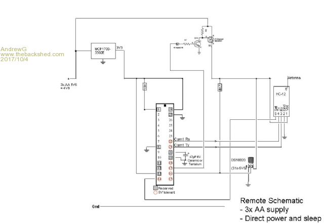 |
||||
| Grogster Admin Group Joined: 31/12/2012 Location: New ZealandPosts: 9975 |
Hard to read....  From what I can see, transistor arrangement looks right. If you post as a GIF image and NOT a JPG, it will show up much clearer. Make sure that you CLOSE the com port when you are not using it, so as to prevent the HC12 trying to run on parasitic power, which would add to your power drain. Smoke makes things work. When the smoke gets out, it stops! |
||||
| Andrew_G Guru Joined: 18/10/2016 Location: AustraliaPosts: 883 |
Grogster, thanks, The GIF version is below (I never knew GIF was clearer yet 1/2 the file size?) You'll see that the transistor arrangement is ~ as per your diagram and that it cuts off the DS18B20 too. Some circuits I've seen (eg the LCD Backpack) have lots of capacitors hanging off the MCP1700 - are they necessary? The listing for the remote is below that - yes I Close the Comm port (or think I do). Cheers, Andrew 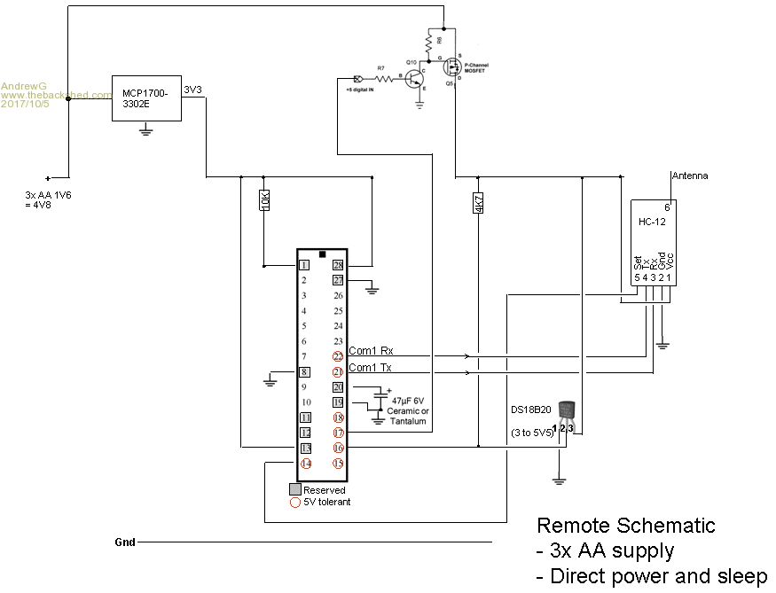 'HC-12 Remote ID4 x 2400 at 10min.bas 'Uses a 28 pin MM170 to take temperature readings via a DS18B20. ' An HC-12 is used to transmit the readings to a base station which displays the readings from several remote stations. ' Each remote station is identified by an ID - this code is for station No. 4. ' 'Notes to self: 'Don't forget the <CR><LF> at the end of NMEA sentences 'I use zzz to flag code I need to check 'Steps to reduce power consumption: ' - set all unused pins to DOUT - done ' - only send a temperature every 10 minutes and then put the MM and HC-12 to sleep in between - done ' - only send a temperature if it differs from the previous reading - done ' - HC-12s to power mode FU2 (necessitates 4,800 baud) - done using Rob Rozee's HC-12 Configuration program ' - Set baud rate to 2400 to increase range - done ' - Set the MM to a slow speed - reduced MM to 20 (any slower & TEMPR returns "1000" = error) ' - Don't need to ground unused pins - not grounded Dim Integer Chksum Dim Float Temp, TempOld Dim String StationID = "4" 'Apply a unique No to each remote station (ID 1 = Base Station) CPU 20 'Set the CPU's speed to the slowest that still enables a TEMPR reading 'Set all unused pins as DOUT 'Leave pins 1, 8, 11, 12, 13, 18, 21, 27 and 28 alone for now SETPIN 2, DOUT SETPIN 3, DOUT SETPIN 4, DOUT SETPIN 5, DOUT SETPIN 6, DOUT SETPIN 7, DOUT SETPIN 9, DOUT SETPIN 10, DOUT 'SETPIN 14, DOUT 'Pin 14 used as the HTC-12 SET signal so is to be set as DOUT anyway SETPIN 15, DOUT 'Pin 16 is used by the TempR command so leave for now SETPIN 17, DOUT SETPIN 18, DOUT 'Pins 21 & 22 are set by the Com#1 Open and Close commands so leave for now SETPIN 23, DOUT SETPIN 24, DOUT SETPIN 25, DOUT SETPIN 26, DOUT Open "COM1:2400" As #1 'Com1 uses pins 21 and 22 for Tx and Rx respectively. 4,800 required for mode FU2. TempOld = 0 'Gets checked each reading. Only sends a value if it differs. PIN(14) = 1 'zzzProbably unnecessary?? Do 'The main loop - it never ends SendTemp 'Read and send the temperature via the HC-12 to the base station ' put the HC-12 to sleep PIN(14) = 0 'Set pin low to enter SETUP mode Pause 50 'Wait at least 40m seconds Print #1, "AT+SLEEP" 'GetResponse 'Check that it responds "OK+SLEEP" - used in debugging PIN(14) = 1 'Return the 'SET' line high again to exit SETUP mode ' put the MM to sleep Close #1 CPU SLEEP 599 'Here to set the CPU sleep time in seconds (600 = 10 minutes) 'After a sleep - the MM wakes up. Then wakeup Comms and HC-12 Open "COM1:2400" As #1 'To wake up a sleeping HC-12, you have to pulse the 'SET' line low again(50mS should do it), 'then return the line high again and WAIT 200mS for the module to reset itself. PIN(14) = 0 ' pin is set low - this enters Command mode Pause 50 'then return the line high again and WAIT 200mS for the module to reset itself PIN(14) = 1 ' pin is high Pause 200 ' HC-12 should now be OK to receive/send data Loop End Sub SendTemp Local String Out$ Local Integer Z Temp = TEMPR(16) ' If Temp = TempOld then 'zzz Omitted whilst testing battery usage ' Exit Sub ' Else ' TempOld = Temp ' EndIf Out$ = CRC$("$,"+Str$(Temp)+"," + StationID) 'This is close to an NMEA 0183 "water temperture" sentence $??MTW... with the StationID exchanged for "C" (Celsius) Print Out$ Print #1,Out$ ' pause 250 'Print #1,Out$ 'zzz Appears to be not needed 'Send it a second time 'Pause 250 End Sub 'SendTemp FUNCTION CRC$(Txt$) 'AS String 'Returns the Txt$ passed to it with "*hh" added, where hh is the NMEA Hex checksum Chksum = 0 FOR n = 2 TO LEN(Txt$) 'n=2 makes it skip the leading $ Chksum=Chksum XOR ASC(MID$(Txt$,n,1)) NEXT n CRC$=Txt$+"*"+HEX$(Chksum,2) END FUNCTION 'Sub GetResponse 'Only used when debugging to check response to "AT+SLEEP" = "OK+SLEEP" ' Local integer i ' Local string x$ ' Tmp$ = "" ' Do ' X$ = Input$(1,#1) ' If X$ = Chr$(13) then ' Exit Sub ' End If ' Tmp$ = Tmp$ + X$ ' Loop 'End Sub |
||||
| Grogster Admin Group Joined: 31/12/2012 Location: New ZealandPosts: 9975 |
If you are going to switch the Vcc to the module using the transistors, you don't need the SET line connection at all - unless you also setup the module inside your code. Just SETPIN 17,DOUT(in your schematic above) and then PIN(17)=1 to turn the HC12 on, and PIN(17)=0 to turn it off. IE: If you are using transistors to turn the module off and on, connect the MM I/O pin to the transistors. If you are using the HC12's SET line and AT commands to sleep the module, connect the MM I/O line to the HC12's SET line. You don't need both. EDIT: Oh, and about the caps - no, you don't. It depends on what processor you are using, and it's specific requirements. Geoff's schematic for the LCD backpack etc, just show all the 100n decoupling caps beside each other for simplicity. With a standard 28-pin MM chip, there is generally only two 100n caps. The 1700-series regulator only needs 1uF of input and output capacitance to be stable. I tend to use 10uF for good luck, X5R MLC type. Smoke makes things work. When the smoke gets out, it stops! |
||||
| Andrew_G Guru Joined: 18/10/2016 Location: AustraliaPosts: 883 |
Hi Grogs -thanks. Good point about not needing both the "switch" and "AT+Sleep". I'll try to set up a test to measure the current with either and make a choice - I guess the switch will win. Re the capacitors, my understanding from your comment is that it is preferable that I have 2x 100n (I have some ceramics) and 2x 10uF as per Geoff's schematic. I'll be using through hole and veroboard. Thanks, Andrew |
||||
| Grogster Admin Group Joined: 31/12/2012 Location: New ZealandPosts: 9975 |
The MOSFET switch WILL win. Although the sleep current is tiny at 22uA or so, that is still 22uA if you want to get specific, and the MOSFET switch when off, will mean the HC12 will not be powered, so won't draw any current at all. MCU's don't like dirty power, and failure to use the correct decoupling caps can(and does) cause some very obscure behaviour from most of them if you don't follow the datasheet's recommendations. For the DIL MM chip, normally just the two 100n's are all that is needed, placed as close to pins 13 and 28 as possible. The PIC32 chip used on the E100 board uses eight 100n caps on all the different power supply pins, and as close as possible. It all depends on the chip, and what it's datasheet says. Smoke makes things work. When the smoke gets out, it stops! |
||||
| Andrew_G Guru Joined: 18/10/2016 Location: AustraliaPosts: 883 |
Grogs, thanks for the advice re the caps. I'll certainly take it. I assume that a through hole 2N7000 would work as a switch instead of the SMD ones? I'll give it a go on breadboard first. Cheers, Andrew |
||||
| CaptainBoing Guru Joined: 07/09/2016 Location: United KingdomPosts: 2171 |
2N7000, although ancient and primitive, exists cheaply in vast quantities - kind of like the Herring of the FET world - I love it!!! Because it is unrefined, 2N7000 (or the BS170) is a good choice generally as a VCC switch for low-medium current. Very high off resistance and low enough that it doesn't really matter when on with <200mA D-S (ish). HOWEVER: you need a P-channel device for the circuit as shown, Dr.Google suggests a BS250., but you might like to hunt around for a more modern device if you are going to have to get one in specially - lower RDS, better VThresh etc. You could use a 2N7000 and drive the gate directly from pin17 but be wary of the voltage drops with battery operation (and the pin floating for a few mS while booting before PIN(17)=0:SETPIN 17,DOUT). You have already seen the voltage go way down before things die. For example VThresh of 2N7000 can be 0.8V to 3.0V so you might find that on tired batteries, you can't provide a sufficiently HI voltage for the FET's gate - they get hot and decompose over time (maybe only seconds) if they are held in the amplification zone (roughly between the upper and lower limits of VThresh). Plus increased RDS (read lower current:thus:voltage) to the HC-12. Using FETs as a switch is a great idea but needs a clean+fast transition between on/off/on. The MM edge is easily fast enough but if you get a lazy FET or low VDD/VCC it might not like the levels. If you do run from a regulated 3.3v supply, you should generally avoid these problems but heads-up. Something else you could try (but not if driving a 2N7000 direct), rather than the 3v3 regulator on the ~4.5 supply, tap the battery stack between cells 2 & 3 to provide the 3v direct to the MM from there. It will mean marginally heavier usage of the first two cells but you could eliminate the regulator and its quiescent current (plus its cost) and still run the HC-12 on 3 cells. The third cell would then form a kind of power boost when needed rather than being in-circuit all the time. This thread has turned into an entirely enjoyable canter with experimentation and measurement - maybe this can help. Do some tests with varying VCCs and watch out for hot FETs! EDIT: while you are at it, put a 100nF cap between pin 1 on the MM and GND to provide a better reset pulse (~1-2mS) and provide a bit of noise immunity. Good luck and have fun! |
||||
| vegipete Guru Joined: 29/01/2013 Location: CanadaPosts: 1179 |
Using these two techniques, (software sleep with the SET pin, and power switching with a FET) how quickly does the HC12 wake up? For example, how long does it take to go from sleep/off to transmitting a byte? Also, in normal use, can the SET pin be left floating (unconnected) or must it be pulled high with a resistor? Visit Vegipete's *Mite Library for cool programs. |
||||
| Andrew_G Guru Joined: 18/10/2016 Location: AustraliaPosts: 883 |
Pete, two good questions! 1) Time to awake (or re-boot) and transmit data - I don't know (perhaps a clever TBSite might?) I couldn't see reference in the manual. I had always though it might be an issue (also the power required to do it) but since I'm only transmitting every 10, or even 30, minutes I haven't worried. When I eventually get my test working I'll try to check. 2) Pullup resistor to unused "Set" pin (#5). The manual says there is an internal 10k resistor (twice, in another spot it says 1k). I have three units operating. One has #5 connected and used to sleep it, two not connected - I cant discern any difference in behaviour. Cheers, Andrew |
||||
| Page 1 of 2 |
|||||
| The Back Shed's forum code is written, and hosted, in Australia. | © JAQ Software 2026 |
