
|
|
Forum Index : Microcontroller and PC projects : Why doesn’t this work?
| Page 1 of 4 |
|||||
| Author | Message | ||||
Grogster Admin Group Joined: 31/12/2012 Location: New ZealandPosts: 9975 |
Hi folks.  Interesting one here - for me. Setup an input with the PULLUP option. Ball-switch between that input and ground. The ball-switch is a captive ball-bearing that can roll backwards and forwards to detect a physical tilt of the unit. The ball-switch is bi-directional, in that a tilt either left or right will complete the circuit through the ball-switch. Tilting forward or reverse is ignored. The problem I have been having is that the input refuses to see the ball-switch when tilted with the pullup option in place. If I remove the pullup option, it works as it should. If I test any suspect ball-switch with a multi-meter, it correctly shows a closed circuit when you tip it over. I figured the pullup option would have been a good idea, to keep the pin from floating, but with that in place, the circuit is extremely unreliable. It MIGHT react to the tilt, but often ignores it completely. Remove the pullup option from the code, and it works every time a coconut. Tilt switch resistance when tilted can be anywhere from zero ohms up to 100 ohms or so, and there is no predictable pattern to that resistance - it seems to vary from switch to switch. I have not seen anything HIGHER then 100R during testing though. Even if the ball-switch was unusually high - say 1k - then with the internal 100k pullup, that means the pin will see about 32mV when the switch is closed, which is well within what the MM should consider a low input.  I don't get it - anyone else got any ideas? I have a work-around for now(don't use the pullup option when setting up the input pin), but I don't really like leaving floating inputs on a design....  One thing I am going to try, is fitting a 10k or 4k7 external pullup to the design, but this is messy as the PCB's are done now, and I hate having to make hacks. One thing I am going to try, is fitting a 10k or 4k7 external pullup to the design, but this is messy as the PCB's are done now, and I hate having to make hacks.  Smoke makes things work. When the smoke gets out, it stops! |
||||
OA47 Guru Joined: 11/04/2012 Location: AustraliaPosts: 1050 |
Grogs, Is this another of your Kiwi euphemisms? Sorry can't think why you are having issues. Could it possibly be switch bounce and maybe you may need to put de-bounce in your software. Graeme |
||||
TassyJim Guru Joined: 07/08/2011 Location: AustraliaPosts: 6538 |
There have been a couple of times in the past where we have been suspicious of the value of the internal pull-up resistors. An external 47-100k will test that theory. I agree that with your readings of the closed resistance there should not be any worries whatever the value of the pull-up. A capacitor across the contacts will help if contact bounce is the problem. Didn't you throw away some nice mercury tilt switches a few years ago? Jim VK7JH MMedit |
||||
redrok Senior Member Joined: 15/09/2014 Location: United StatesPosts: 209 |
Hi All; I won't address the uMite pull-up, PU, resister problem. I have some thoughts about the switch itself. I've made some "ball and pin" switches in the past for use as limit switches in solar tracker applications. The problem I've had was with steel ball bearings and tin plated wire-wrap pins. Both the balls and pins tend to have a minute thin oxide layer. This layer is very thin and capable of resisting 3.3V. If the contact is closed very slowly there is not enough force to break through the oxide. Since the PU is quite weak there is not enough current to burn through the oxide either, especially at 3.3V. 1. My solution was to put a 0.1uF from the contacts to ground. This capacitor has enough charge to break through the oxide when closed. This was a highly reliable solution. 2. A second solution was to plate the ball with gold and use gold wire-wrap pins. Gold has no oxide layer so the contact was reliable. (Don't use a capacitor with gold plating as it's fragile.) 3. I would suggest using an external PU of, say, 1K or so. 3mA may be enough to get through the oxide. redrok |
||||
| Grogster Admin Group Joined: 31/12/2012 Location: New ZealandPosts: 9975 |
Thanks very much for the ideas folks. I will try the cap first. It is easy to add, and can be hidden under the PCB where no-one will see it.  Don't really want to use low-value pull-ups, as they will increase the standby current, and thus, affect the life of the battery which is a very nice two weeks or so at the moment without recharge. I will keep the thread posted. EDIT: @ OA47 - Have you never heard that term before? Kiwi's use it quite a bit, so I figured that our Aussie pals would have also heard of it. Smoke makes things work. When the smoke gets out, it stops! |
||||
| Warpspeed Guru Joined: 09/08/2007 Location: AustraliaPosts: 4406 |
You might also like to think about using a wide opto fork. No oxides or contact bounce and pretty reliable. Cheers, ĀTony. |
||||
| Grogster Admin Group Joined: 31/12/2012 Location: New ZealandPosts: 9975 |
Sounds ideal - where can I find these 'opto-fork's' ? I much prefer isolated input via opto anyway, but all I knew of was opto-couplers in the form of NPN transistors. The 100n across the ball-switch did not help. This is on units where the PULLUP option is still present. In fact, it made it worse, as the cap charge kept the switch input 'on' all the time, and the unit went off even when tipped back flat again. Nice idea though. Disable the PULLUP on that same unit, remove the cap, and no problems. Put the PULLUP back on again, and it won't trip. *scratching head*  Smoke makes things work. When the smoke gets out, it stops! |
||||
| Warpspeed Guru Joined: 09/08/2007 Location: AustraliaPosts: 4406 |
The wider optical forks have a typically a 5mm gap. You can get photo transistor output, schmidt trigger logic level output, surface mount or through hole type. This is just an initial example I found very quickly: http://www.mouser.com/ds/2/307/en-ee_sx3350_4350-1076535.pdf Its also possible to saw any type of opto fork in half and spread the halves slightly further apart. The advantage of that is the two halves are optically matched for wavelength. They could be glued to a piece of clear plastic tube for the steel ball. Probably better if you can use a standard optical fork without cutting, as both sides will stay in optical alignment better. It will give a very clean and very reliable signal once you work out the mechanical details. Cheers, ĀTony. |
||||
| Grogster Admin Group Joined: 31/12/2012 Location: New ZealandPosts: 9975 |
Ahhh, I see what you are referring to. I call those 'Opto-interrupters'. Here is a photo of the guts of a sensor I cut open: 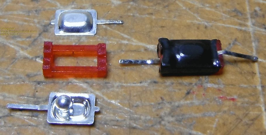 You can see that when the unit is tilted, the ball rolls to one end or the other, and forms a circuit with the top and bottom cups. Extremely simple, and effective - once I disable the PULLUP option..... Smoke makes things work. When the smoke gets out, it stops! |
||||
| Warpspeed Guru Joined: 09/08/2007 Location: AustraliaPosts: 4406 |
Just another idea... A swinging pendulum and an opto interrupter might be another option that may be easier to home brew than a ball in a tube. I suppose it depends on the purpose. Cheers, ĀTony. |
||||
Bryan1 Guru Joined: 22/02/2006 Location: AustraliaPosts: 2099 |
Another idea is just use a small neo magnet and a 1101 hall effect sensor |
||||
| redrok Senior Member Joined: 15/09/2014 Location: United StatesPosts: 209 |
Or a small magnet moving near small encapsulated read switches. Example Read Switches Unlike opto-isolaters they don't, themselves, consume any current. Plus, the contacts are sealed inside glass. redrok |
||||
| Alastair Senior Member Joined: 03/04/2017 Location: AustraliaPosts: 161 |
G, The fact that it works ok with no pullup and flaky with it on says the 'pull down' effect of the ball is poor. Could there be a slight coating (oil) on the ball. Give it and the cup a clean with some solvent and see what happens. Probably silly but ... Cheers, Alastair |
||||
| Grogster Admin Group Joined: 31/12/2012 Location: New ZealandPosts: 9975 |
Thanks for all the replies, chums. The pendulum idea and opto is OK, but an earlier idea used this very same concept(ball-interrupter thing, but you can no longer get them), but the opto would not operate without at least 3-5mA of LED current, and that current being sucked all the time 24/7, kills the battery inside two days. I like the idea, but that was why I went with the ball-switch, as they consume zero standby current. The MM then goes to sleep to save even more battery power, and just wakes up when the ball-switch is tilted. I also very much like the idea of the magnet and reed switch. That is one idea I will look into for any future boards, as it is a zero-standby current concept. I also looked at accelerometers and hall-sensors briefly, but they both suck current in standby, which ultimately was why I was drawn to the ball-switch concept. What irritates me greatly about this problem, is that the prototype did not have this issue - even with the PULLUP option enabled. It worked every time.(a coconut!) So it was a little unexpected to find that once I started building units, that some of them would not respond when tipped up!   Ain't that just typical!? (rhetorical!) Ain't that just typical!? (rhetorical!)With the pullup option removed from all units, ALL of them now respond fine. Strange. I don't REALLY care that much, but I am still scratching my head a little over what should not be, and also leaving an input floating makes me nervous. I will try some external pullups next just to see what happens.(with PULLUP option left off) Smoke makes things work. When the smoke gets out, it stops! |
||||
| Warpspeed Guru Joined: 09/08/2007 Location: AustraliaPosts: 4406 |
Zero standby power probably limits you to the reed switch idea. That should work very well because these switches open and close very positively, and being fully sealed there can be no dirt or oxidation. Standby power can also be greatly minimized by only powering up a sensor while it is being read. Say for one millisecond every second. That would turn 5mA into 5uA average. Thinking about that a bit more, many of these opto devices are pretty fast. Its possible to pulse the LED at 100Khz (or more) and see a square wave coming out of the logic level detector side. You could write some software: Energise LED Read opto De energise LED The power for the LED might only need be a couple of instruction cycles long. That could be repeated at a few Hz, and the total power might be kept very low. Same with a Hall effect sensor which also respond very quickly. It opens up a few more possibilities Cheers, ĀTony. |
||||
| Grogster Admin Group Joined: 31/12/2012 Location: New ZealandPosts: 9975 |
Yes, you make good points there. Food for thought. Smoke makes things work. When the smoke gets out, it stops! |
||||
| kg4pid Regular Member Joined: 08/03/2015 Location: United StatesPosts: 50 |
Have you connected a regular switch in place of the ball switch to verify where the problem is. Have you placed a 100k PULLDOWN resister on the input with the internal pullup enabled and then measured the voltage on the input pin? It should be about half of the supply voltage if the internal pullup is working. Max |
||||
| Grogster Admin Group Joined: 31/12/2012 Location: New ZealandPosts: 9975 |
Good idea, will have a play. I am sure the ball-switch is the issue, but not entirely sure WHY. I suspect that redrok is correct, and that it is a very thin oxide layer. I suspect that is probably why my multimeter says they are a good short circuit when tipped, as the multimeter on low-ohms probably passes 5mA or so via the probes for the test, whereas the MM input will not - it will be micro-amps if anything. Alistair mentions something similar at the top of this page, but when I examined a switch I cut open under the microscope, the ball and cups look very clean. But that does not necessarily prove anything if an oily layer was there, you probably could not see it under the scope anyway!  Everything works perfectly with the pullup option disabled.....  Smoke makes things work. When the smoke gets out, it stops! |
||||
| Warpspeed Guru Joined: 09/08/2007 Location: AustraliaPosts: 4406 |
I recently built a battery monitoring system for thirty Lithium cells that used relays to individually switch each cell across a high impedance floating voltmeter. The grand plan was to also couple an individual cell charger/discharger through the same relay contacts for balancing the cells under software control. It was hopeless !!! The relay contacts gave horrible intermittent contact for high impedance voltage measurement. The same contacts worked fine for feeding 100mA in or out of each cell, but I needed to measure the voltage of each cell first for monitoring, then let software determine if any power needed to be switched. I think your steel balls may be just as big a headache as my relay contacts, and its just not workable. What I am using now instead of physical relays are optically isolated mosfet switches and the system works fine. Mechanical contacts are very bad news unless there is sufficient power to break through any dirt, grease or oxide. Cheers, ĀTony. |
||||
| Alastair Senior Member Joined: 03/04/2017 Location: AustraliaPosts: 161 |
A bubble burst in my long term memory. The term 'whetting current' popped up. In electrical engineering, wetting current (sometimes also spelled as whetting current in archaic sources) is the minimum electric current needing to flow through a contact to break through the surface film resistance. The film of oxidation occurs often in areas with high humidity. Wetting current - Wikipedia https://en.wikipedia.org/wiki/Wetting_current Whilst still a Uni student I did holiday work for the father of a school chum. He ran an electrical engineering company which dealt with big motor/generator sets. I recall that to minimise contact burning they had a primer current that 'whetted' the contacts before the serious current came on. Don't recall how they managed the timing. Cheers, Alastair |
||||
| Page 1 of 4 |
|||||
| The Back Shed's forum code is written, and hosted, in Australia. | © JAQ Software 2026 |
