
| Menu | JAQForum Ver 19.10.27 |
| Menu | JAQForum Ver 19.10.27 |
Forum Index : Solar : Looking for open source inverter code
Hi all, I am in the process of building a 1kW 24V Inverter for learning purposes. The design is similar to the typical EGS002/EG8010 low frequency design. However, instead of using the EG8010 I have used an Arduino Nano. I did this because I wanted to be able to adjust aspects such as switching frequency and PID gains for learning purposes. Does anybody have open source inverter code that attempts to replicate the EG8010? I have uploaded my current schematic and code. The main thing I am struggling with at the moment is voltage feedback/regulation using PID. 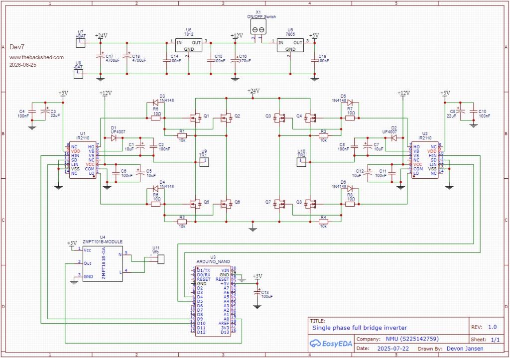 // 20kHz Unipolar SPWM with PID control // ZMPT101B module used for voltage feedback #include <avr/io.h> #include <avr/interrupt.h> #include <ZMPT101B.h> #define SENSITIVITY 450.0f // Sensitivity of the ZMPT101B voltage sensor module ZMPT101B voltageSensor(A0, 50.0); // D10/D9 20kHz SPWM, D4/D5 50Hz square wave // HIN1-D10, LIN1-D9, HIN2-D4, LIN2-D5 // Total samples per cycle: 20kHz/50Hz = 400 // ICR1 = (Micro clock (16Mhz)/ Carrier frequency)/2 = (16Mhz/20kHz)/2 = 400 // Look up table is for a half cycle (200 table entries) with a max value of 400 (100% duty cycle) volatile float percentMod = 0.0; float Kp = 0.001; float Ki = 0.0000; float P = 0.0; float I = 0.0; float voltageSetpoint = 230.0; unsigned long lastControlTime = 0; int phs; //---------------------------------Look Up Table for 20kHz carrier----------------------------------- int lookUp1[] = { 0, 6, 13, 19, 25, 31, 38, 44, 50, 56, 63, 69, 75, 81, 87, 93, 99, 106, 112, 118, 124, 130, 135, 141, 147, 153, 159, 165, 170, 176, 182, 187, 193, 198, 204, 209, 214, 220, 225, 230, 235, 240, 245, 250, 255, 260, 265, 269, 274, 278, 283, 287, 292, 296, 300, 304, 308, 312, 316, 320, 324, 327, 331, 334, 338, 341, 344, 347, 351, 354, 356, 359, 362, 365, 367, 370, 372, 374, 376, 378, 380, 382, 384, 386, 387, 389, 390, 392, 393, 394, 395, 396, 397, 398, 398, 399, 399, 400, 400, 400, 400, 400, 400, 400, 399, 399, 398, 398, 397, 396, 395, 394, 393, 392, 390, 389, 387, 386, 384, 382, 380, 378, 376, 374, 372, 370, 367, 365, 362, 359, 356, 354, 351, 347, 344, 341, 338, 334, 331, 327, 324, 320, 316, 312, 308, 304, 300, 296, 292, 287, 283, 278, 274, 269, 265, 260, 255, 250, 245, 240, 235, 230, 225, 220, 214, 209, 204, 198, 193, 187, 182, 176, 170, 165, 159, 153, 147, 141, 135, 130, 124, 118, 112, 106, 99, 93, 87, 81, 75, 69, 63, 56, 50, 44, 38, 31, 25, 19, 13, 6, }; void setup() { // Initialising timer registers // WGM mode 8 is used (Phase Correct PWM Mode) TCCR1A = 0b10110000; TCCR1B = 0b00010001; TIMSK1 = 0b00000001; ICR1 = 400; // Counter TOP value for timer 1 sei(); // Enable global interrupts DDRB |= (1 << PB1) | (1 << PB2); // D9 and D10 as outputs DDRD |= (1 << PD4) | (1 << PD5); // D4 and D5 as outputs PORTB &= ~((1 << PB1) | (1 << PB2)); // Initially set D9 and D10 LOW PORTD &= ~((1 << PD4) | (1 << PD5)); // Initially set D4 and D5 to LOW percentMod = 0; for (int i = 0; i < 70; i++) { // Soft Start (~3 seconds) percentMod = percentMod + 0.01; delay(40); } Serial.begin(9600); voltageSensor.setSensitivity(SENSITIVITY); // Sensitivity of ZMPT101B } void loop() { // Run voltage control approximately every 20 ms (50Hz) if (millis() - lastControlTime >= 20) { lastControlTime = millis(); float voltageFeedback = voltageSensor.getRmsVoltage(); float error = voltageSetpoint - voltageFeedback; // Proportional term P = Kp * error; // Integral term if (abs(error) < 20.0) { //Only enable integral term after soft start I += Ki * error * 0.02; } // Limit I term to prevent windup if (I > 0.1) I = 0.1; if (I < -0.1) I = -0.1; // PI controller percentMod += P + I; // Clamp modulation index if (percentMod > 0.97) percentMod = 0.97; if (percentMod < 0.10) percentMod = 0.10; Serial.print("V = "); Serial.print(voltageFeedback); Serial.print(" Error = "); Serial.print(error); Serial.print(" Mod = "); Serial.println(percentMod); } } ISR(TIMER1_OVF_vect) { static int num; static int ph; static int dtA = 0; static int dtB = 5; if (num >= 199) { if (ph == 0) { // OC1A as SPWM out TCCR1A = 0b10110000; // clear OC1A, set OC1B on compare match dtA = 0; // no dead time dtB = 5; // adding 300ns dead time to OC1B } else { // OC1B as SPWM out TCCR1A = 0b11100000; // clear OC1B, set OC1A on compare match dtA = 5; // adding 300ns dead time to OC1A dtB = 0; // no dead time } ph ^= 1; } // SPWM duty cycle OCR1A = int(lookUp1[num] * percentMod) + dtA; // Duty cycle is controlled by percentMod OCR1B = int(lookUp1[num] * percentMod) + dtB; // dtA and dtB introduce a deadtime of ~300ns num++; // Next lookup table sample // Generating two 50Hz square waves that are 180 degrees out of phase if (num >= 200) { if (ph == 1) { digitalWrite(5, LOW); digitalWrite(4, HIGH); phs = 1; } else { digitalWrite(4, LOW); digitalWrite(5, HIGH); phs = 0; } num = 0; } } |
||||||
Dev there is a thread about doing what you seem to want to do, using Wiseguys boards and a nano' have a look at this link wiseguy inverter boards good luck pete |
||||||
 |
The Back Shed's forum code is written, and hosted, in Australia. |


