Posted: 01:17am
31 May 2026
 Copy link to clipboard Copy link to clipboard |
Solar Mike
Guru

|
|
|
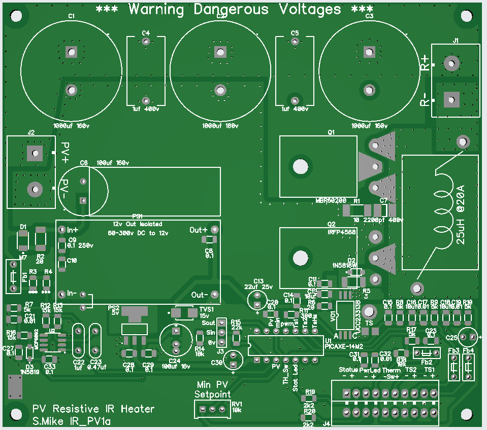
Drawn up enough of the schematic to establish no errors on the pcb, haven't included the CPU in the drawing as its marked up on the pcb. Power: All run off the PV, the PV voltage will shift dramatically, the cpu power is via a diode so will fluctuate less so. PV voltage sensing, set up resistors for 1mA, depending on slightly higher than max unloaded PV voltage, I'm using 130v so total R of 130k. 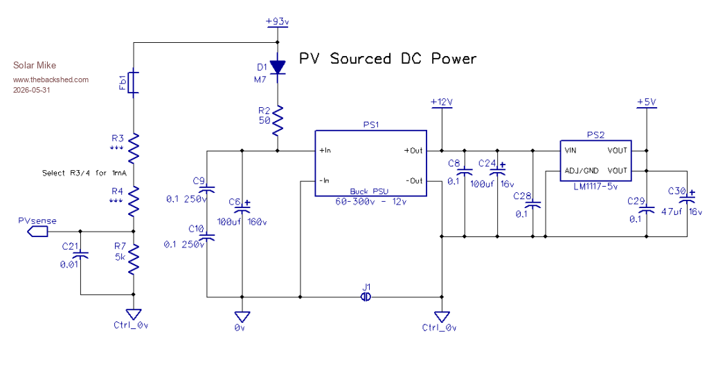 PV Sense Filter: 3 stage Low pass filter around 10hz will eliminate most RFI switching noise and allow stable mppt operation. 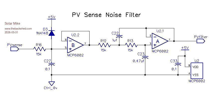 External Thermostat and heating panel NTC resistor sensing. Probable run shielded wires or twisted pair to thermistors. 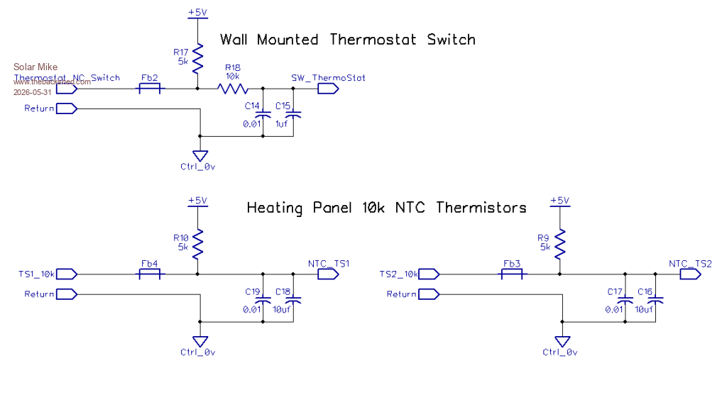 Buck power stage, using "E-Diode" mosfet driver, single 200v mosfet and dual catch diode, wind inductor on one of those MS225125-2 sendust cores, not too worried about ripple current here 25-50uH should be plenty; just want to slow down the sharp on\off transitions to more triangular waveform. Use around 10Khz PWM for lower ripple current on the 3 x 1000uf electro's rather than slow high current "bit bang" operation. I made something similar to this a few years ago to heat a hot water element from 240 Vdc pv array, used a 555 timer and 10,000uf 400v capacitor, worked pretty well; but requiring a thermostat and thermistor heat sensing, its easier to use a $5 cpu. Will see how this performs, by the time I make up the heater panels it may be easier to gut and use a $40 reflector type dual bar heater and place all the PV panels in series for 200v. Cheers Mike 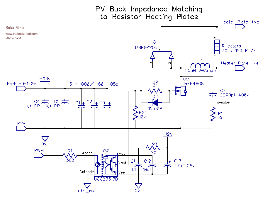 |