| Menu | JAQForum Ver 19.10.27 |
| Menu | JAQForum Ver 19.10.27 |
Forum Index : Microcontroller and PC projects : hardware timer that can fire an interrupt ?
is there a capability to have a hardware timer that can fire an interrupt ? for example : Set the timer in 1 microsecond tick. have two compare values. 140 and 230 when the timer count passes 140 it fires interrupt1. when it passes 230 it fires interrupt2 This is a functionality many microcontrollers have. timer with events. Can't find something like this in the RPxx. I need microseconds. longest "tick" acceptable would be 32microseconds. I have an external event that happens every 4 milliseconds and i need to react to that with a granularity of 128 steps. The idea is to trigger an interrupt from the pin change and launch the timer. When the first compare hit i need to take an action ( jiggle some pins ) when the second compare hits there is another action ( again jiggle some pins) each interrupt handler is very short. like 4 instructions, no loops. it's only i/o state changes |
||||||
Sounds like a job for the PIO. |
||||||
Hi vincent, So there is an external signal (pulses) with a repeat rate of 4ms. You do not need to measure that signal, but in reponse to that signal (synchronous), after 140us, and 230us you output a certain pattern on a set of GPIO pins (2 different patterns). Is that pattern fixed, or should it be under control of MMBasic ? This is something PIO can do. - wait for an edge on GPx - wait 140us = T1 - output pattern A - wait 90us (230-140) = T2 - output pattern B - loop As long as that pattern is maximum 5 adjacent GPIO pins it sounds easy. Otherwise it is more complicated. PIO can do this autonomous. It can also receive values for T1, T2, A and B from MMbasic through PIO FIFO. Regards, Volhout Edited 2025-09-12 05:20 by Volhout |
||||||
roughly correct. there is some more stuff going on on the background but the core is an autonomous process. What this thing does is create two markers on an analog oscilloscope tube. When the sweep starts ( every 4 milliseconds ) i launch the timer. Here is the exact thing that needs to happen. pin1 : a falling edge arrives : fire interrupt handler 1. The scope signals it is in beam retract. ready to start a sweep Pin1 : a rising edge arrives fire interrupt handler 2. This is the scope signalling it has started the sweep The delay between falling and rising is short. 50 microseconds tops. so the ISR will be short. only update T1 and T2 (the user may have changed the two time counts.) interrupt handler 1: { stop and reset the timer load T1 and T2 , possible T3 values into "compare" ' load the marker positions } interrupt handler 2: { start timer } T1 or T2 is crossed : { Stop the main timer pin2 goes high ' this enables the marker generator if T1 was the trigger : make Pin4 high if T2 was the trigger : make pin5 high wait 2 microseconds ' wait for the trace to go up pin3 goes high ' switch trace to low wait 2 microseconds ' pin2 goes low ' turn marker off pin3 goes low ' turn trace back to up ready for the next event pin 3 and 4 need to go low in sequence. it can't happen at the same time continue the timer. we know we lost 4 microseconds + a some instruction cycles so the "higher up" software can compensate T2 for that. the timer can keep going as it will reset when pin1 moves. T2 expires : same as T1. Same handler. It is ok for the timer to halt while it is performing the ISR. The 2 microsecond time is not known yet. it could be more. Would be nice if that was programmable through a variable as well.(T3) a timing diagram... <------------------ 4 mS-------------------------> Pin 1 : TRIG --____________--------------------------.....-------_____ ^load timer registers ^ start timer T1 or T2 hits : P2 ____------------------------------------------______________ P3 _________________________----------------------_____________ on T1: P4 ____---------------------------------------------------.... On T2: P5 ____---------------------------------------------------.... <------T3-----------><------T3-----------> since we have 4 milliseconds that is 4000 microseconds. 12 bits is 4096 steps. so we can use a 16 bit hardware counter for this This is a hardware process that runs forever from powerup to powerdown. Only T1 and T2 and possibly T3 get updated on every falling edge of pin 1 pin allocation is flexible. hardware has not been designed yet. The "higher up" program does other things. Pin 4 and 5 can only be SET by the timer. the higher up software will reset them if desired in the handler for interrupt1 They are control signals for samplers. The conversion takes time. If a sampler is ready the control signal (either P4 or P5 , never both ) will be made low. This opens the sample gate. If the timer expires on T1 sample gate closes (Pin4) The same for Pin5. The gates will never be open during the same sweep. i can only take 1 sample per sweep, either on T1 or on T2. So we may be able to get away with only one pin but it needs to be switched by software to wither use T1 or T2 as the toggle point. The timer can only "SET" the pin. clearing happens in software. This could also be an argument passed to the PIO the logic could be simplified: Possible arguments passed to PIO block: Time1(16bit) : time to marker 1 time2(16bit) : time from marker 1 to marker 2 time3(16bit) : time in marker bit1 : if high : clear Pin4 at timer start, and make bit1 low again (when the timer starts) Bit2 : if low : Set Pin4 at T1. If high : set pin4 at T2 It's really simple logic. can sit in a small CPLD or even be made with some 74393 loadable counters. and some gates. But it would be nice to have it done by the processor. thanks Edited 2025-09-12 06:12 by vincenthimpe |
||||||
It can't be done directly in MMBasic as the interrupts are not handled in hardware with the exception of a counter. All other interrupts are polled after each command is processed. A PIO is the only way to go, I think. |
||||||
Vincent, More questions. 1/ Are you using an RP2350, or a RP2040. I specifically ask this because the 2350 can use the FIFO as a register bank, or a FIFO. The 2040 only as a FIFO. A 2350 would be much easier to implement on MMBasic side. 2/ I may have missed it, but what is the envisioned resolution needed for T1, T2 and T3. Originally you talked about 32us, later there is mention of 2us. 3/ You mention outputs are only SET by PIO, MMBasic clears the outputs. Are you sure MMBasic can clear the signals between T1 and T2 ? Volhout P.S. when outputs are under PIO control, MMBasic cannot clear them (unless we do a direct register write..a poke). Edited 2025-09-12 16:17 by Volhout |
||||||
If I interpret your description correct, below could be a PIO implementation The MMBasic program writes a specific value in FIFO, and PIO runs "unsupported" using these values until they change. The only thing unclear is the "clearing of outputs" by MMBasic. Slaved to an analog oscilloscope, produce markers. Pin assignment GP0: input triggers both MMBasic (falling edge) and PIO programs (rising edge) GP1: main output GP2: T3 time slaved output MMBasic communicates with PIO through FIFO Using FIFO in non-blocked mode, so PIO can maintain running even if MMBasic is late FIFO 32 bit word assignment 31....20 = 12 bit value for T2-2*T3 19.....8 = 12 bit value for T1 7...0 = 8 bit value for T3 Generic: in PIO program X is the count-down counter for T1, T2, T3 Y stores the T3 value for 2'nd use 'High level PIO program ------------------------------ WAIT GP0=0 'make sure there is a falling edge, so the rising edge is accurate. (MMBasic starts here) SET Y,0 'clear Y OUT Y,8 'get T3 value from FIFO SET X,0 'clear X OUT X,12 'get T1 value from FIFO in X SET PINS,0 'clear all GP1/GP2 WAIT GP0=1 'start of timer T1 :label1 JMP X--,label1 'count down until X=0 SET PINS,&b01 'GP1 high, GP2 low MOV Y,X 'get timer T3 value in X :label2 JMP X--,label2 'count down until X=0 SET PINS,&b11 'GP1 high, GP2 high MOV Y,X 'get timer T3 value in X :label3 JMP X--,label3 'count down until X=0 SET PINS,&b01 'GP1 high, GP2 low between here and T2 we need MMBasic to reset GP1 This can be performed by a direct execution of SET PINS,0 OUT X,12 'get (T2-2*T3) value from FIFO in X :label4 JMP X--,label4 'count down until X=0 SET PINS,&b01 'GP1 high, GP2 low MOV Y,X 'get timer T3 value in X :label5 JMP X--,label5 'count down until X=0 SET PINS,&b11 'GP1 high, GP2 high MOV Y,X 'get timer T3 value in X :label6 JMP X--,label6 'count down until X=0 SET PINS,&b01 'GP1 high, GP2 low JMP 0 'restart loop for next cycle We can also run 2 PIO state machines, one for T1 and one for T2, so they become completely independent. Volhout Edited 2025-09-12 19:30 by Volhout |
||||||
Hi Vincent, For you to try out, a possible PIO example of the marker generator. Yellow trace = GP0 = input signal Green trace = GP1 = T1 output signal (here the PIO pulls it low at falling edge input) T1=128uS T2=500us Blue trace = GP2 = the T3 signals T3=50uS 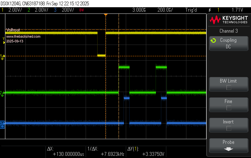 This is for T1 and T2. The P4 and P5 signals are not implemented yet. You can define both state machines drive the same GPIO's if you like. Both state machines run the same program, but can use different FIFO's and IO's. Note that the code has become more complex since I wanted to run it also on the RP2040, hence I had to use FIFO, and make a work around to prevent empty fifo's. Here is the code I used. 'Vincent OsciMarker OPTION EXPLICIT OPTION DEFAULT NONE 'trigger input MMBasic (define NOT as PIO pin) setpin gp0,din setpin gp1,pio1 setpin gp2,pio1 setpin gp3,pio1 setpin gp4,pio1 'pio program 'trigger at rising edge gp0, then wait time T1(2) and output T3/T3 patern pio assemble 1,".program marker" .line 0 set pindirs,&b11 'set the output pins to output set pins,0 'both low .label lab0 wait 0,pin,0 set pins,0 'both low pull noblock mov X,OSR 'make a local copy in X for use if empty fifo out Y,16 'copy FIFO 16 bits in Y = T1(T2) wait 1,pin,0 .label lab1 jmp Y--,lab1 'count down 1 tick per clock for time T1(T2) set pins,&b01 'GPn high out Y,16 'get the T3 value into Y' .label lab2 jmp Y--,lab2 'count down 1 tick per clock for T3 set pins,&b11 'GPn, GPn+1 high pull noblock 'pull a new copy mov X,OSR 'make a local copy in X for use if empty fifo out Y,16 'remove old T1(T2) value out Y,16 'copy FIFO 16 bits in Y = T3 .label lab3 jmp Y--,lab3 'count down 1 tick per clock for T3 set pins,&b00 'GPn,n+1 low jmp lab0 .end program list 'configure PIO 1 state machine 0 dim f%=1e6 'PIO tick = 1us dim s%=pio(shiftctrl 0,0,0,0,0,1) 'shiftdirection out is right (LSB) dim p0%=pio(pinctrl 0,2,,gp0,,gp1,) 'gp0 in, gp1,2 set pio init machine 1,0,f%,p0%,,s%,0 'start adress = 0 'configure PIO 1 state machine 1 dim p1%=pio(pinctrl 0,2,,gp0,,gp1,) 'gp0 in, gp3,4 set pio init machine 1,1,f%,p1%,,s%,0 'start adress = 0 '------------------------- MMBasic program ------------------------ 'generate 4ms test pulses using a PWM channel on GP5 setpin gp5,pwm pwm 2,250,,98 '2% low pulse at 250Hz 'connect gp5 with a wire to gp0 (the trigger input) Van dim T1% = 128 'us dim T2% = 500 'us dim T3% = 50 'us dim FIFO0% = T1% + (T3%<<16) dim FIFO1% = T2% + (T3%<<16) 'load FIFO's and run PIO's PIO START 1,0 PIO WRITE 1,0,1,FIFO0% PIO START 1,1 PIO WRITE 1,1,1,FIFO1% do 'do whatever you want to do here. loop Play with it and let me hear what you think. At any time you can write a new value in the FIFO, and the PIO program will start using the new value. To get microsecond accurate you may need to compensate the T1/T2/T3 values for execution time of the PIO (for exactly 128us you may need to program T1 as 125). Volhout Edited 2025-09-13 05:38 by Volhout |
||||||
@#$@#$@ i was writing a reply and the forum timed out. now i have to rewrite it. stupid forum This is amazing work I think we can simplify things. I've been working on the hardware a bit open source project : PDF documentation : - Pio only listens to rising edge of P1. The decision to launch is taken externally (hardware) - We can use the WAIT (sideload?) instruction , no need for T3. it is a constant decided at design time example set pins , &b00 [31] 2 values : T1 and T2 , each 16 bit so they can go in one FIFO. no need for T3. hardcoded as WAIT 2 flags. FLAG1 and FLAG2 all 4 pins are under PIO control now. 1 input pin (P1) to listen for the "start" (rising edge) 3 output pins. MEN,MPOL,SAMPLE simplified logic state machine : BASIC loads FIFO's with T1, T2, and flags. we can use 4 fifos. one for each parameter. no need to be stingy with the fifos. this removes the need for shift operations in basic. trying to keep things fast and simple. BASIC decides when to start the pio. The BASIC interrupt handler will execute the PIO START at the appropriate time. (there are other logic conditions going on, not of concern to the PIO code) the PIO doesn't seem to have the ability to alter an individual pin. or perform logic operations. can it load data from a fifo onto pins ? coudn't figure that out either. ---- BASIC tells the PIO to start -------- MEN, POL = 0 ' these two pins go low SAMPLE = FLAG1 ' this one depends on Flag 1 LOAD Y from Fifo1 WAIT for PIN1 to go high Decrement Y till zero if F2 = 0 then SAMPLE = 0 MEN =1 WAIT 20 MPOL =1 WAIT 20 MEN,MPOL = 0 LOAD Y from Fifo2 Decrement Y till zero if F2 = 1 then SAMPLE = 0 MEN =1 WAIT 20 MPOL =1 WAIT 20 MEN,MPOL = 0 STOP Edited 2025-09-13 06:09 by vincenthimpe |
||||||
We can maybe simplify it even more. Instead of mucking with flags : Use 2 PIO machines. The first machine only does the marker on pins 1 and 2. it does not need to make any decisions - Set output pins 00 - wait for rising edge on input - wait for time 1 - set output to 10 and use WAIT to halt for 20 cycles - set output to 11 and use WAIT to halt for 20 cycles - set output to 00 - wait for time 2 - set output to 10 and use WAIT to halt for 20 cycles - set output to 11 and use WAIT to halt for 20 cycles - set output to 00 - stop This gets launched from MMBASIC The second machine does this : Set output 0 - wait for rising edge on input ( same input as machine 1 . if not possible we'll sacrifice an additional pin ) wait for time T3 set output to 1 - stop This gives me the flexibility to alter the sample point at will. I only start the second machine when i want. The advantage is there is no need for decision logic in the PIO machines and we eliminate the passing of Flags as well. T3 is calculated at BASIC level ( t3 = t1+constant or T1+T2+constant , where constant is the accumumlation of "WAIT") |
||||||
That may add some variability to the timing. The Pico has to carry out background "housekeeping" tasks (eg maintaining USB system) that affect how long it takes to execute Basic commands. Up to 15µS variation, occasionally more. The PIO is immune to this. eg > clear : dim integer n, a(1000) :dim float t > for n%=0 to 1000:t=timer :pause 0.1 :a(n%)=(timer-t)*1000 : next :? math(max a()) - math(min a());"uS variation" 15uS variation > for n%=0 to 1000:t=timer :pause 0.1 :a(n%)=(timer-t)*1000 : next :? math(max a()) - math(min a());"uS variation" 13uS variation > for n%=0 to 1000:t=timer :pause 0.1 :a(n%)=(timer-t)*1000 : next :? math(max a()) - math(min a());"uS variation" 12uS variation > > ? math(max a()), math(min a()), math(mean a()) 131 119 119.0669331 > > for n%=0 to 1000:t=timer :pause 0.1 :a(n%)=(timer-t)*1000 : next :? math(max a()) - math(min a());"uS variation" 17uS variation > for n%=0 to 1000 : if a(n) > 120 then : ? a(n) : endif : next 133 121 136 122 122 121 121 121 121 121 121 121 121 121 121 121 121 121 121 121 121 121 121 121 121 121 121 121 121 121 > Edited 2025-09-13 10:51 by phil99 |
||||||
Fully understood. All the basic program does is set off both PIOs A BASIC interrupt handler is attached to the falling edge of a pin. T1 and T2 already contain the necessary times. Activetrace is a flag set by the main program that states we need to start the PIO for this run . I deliberately do not perform the compare inside the ISR. the flag is set by "slow logic" outside the ISR. the slow logic has 5x4mS to process all the things before it needs to set "activetrace" back high . The sampling is running even slower. The sampling happened under control of PIO2 and has completed during the last run. We may not be ready after 5 sweep processing that sample. there are 4 a/d conversion to perform , plus a bunch of math and updating displays. It should be doable before we hit the next activetrace. if not, the logic will hold of and let this activetrace pass without setting the "needsample". we cant sample at both T1 and T2 anyway. we have to alternate. the converters take too much time to give the reading. They need about 240 microseconds each + the data transport over i2c so there is no way i can sample in a short interval. i need at least 4x(240 microseconds + i2c transport) to get the data. IF the time between T1 and T2 is less than that i can't sample at T2. So i sample T2 on the next go-around. Simple ping-pong logic. I am not using the on board ADC. They are noisy and i need to control the voltage reference to avoid floating point math. The ADc uses a 2.048 volt (it's a 12 bitter) reference. So ever "step" is exactly 0.5mV. Since my maximum voltage to digitize is 2 volt a can just shift the data one bit right to ditch the last bit and get rid of some noise. that gives me 11 bits or 2.048 volt full scale. No need for floating point math. If i read 1234 that is 1.234 volt. There is a lot of hardware trickery in this system to gain speed. The software is very minimal. The analog signals are stored in Sample/hold hardware. so i can digitize them . it is important that all 4 channels are sampled at the exact same time. The Pio2 generates that point. When it's output goes low( at the start ) the sampling gate opens and the sampler capacitors (4, one for each signal) follows the analog signal. when the PIO2 time value expires it shuts off the sampling gate. The last analog voltage is now stored on 4 capacitors. We have time to digitize those values. falling_edge_handler: if activetrace then Load T1 and T2 in PIO1 Load T3 in PIO2 Start PIO1 if needsample Start PIO2 end if sweep = sweep +1 end falling_edge_handler That's all it does. Edited 2025-09-13 13:43 by vincenthimpe |
||||||
I can modify the current program to the “even simpeler” proposal. Or do you want to challenge yourself to do it.? Maybe I can spend Some time during the weekend. Volhout P.s. The timing for the falling edge handleiding may be critical. But I have ideas , in case it does not work. |
||||||
i have a 3450 board on order. should be here sunday. I'll give it a swing I need to understand how the PIO works for my own sanity. The official datasheet is horrendous to understand. i've never seen something so convoluted in my life, and i have designed processors. It would be easier to understand if they would just publish the internal block diagram or the VHDL model of the PIO machine. that way we could simulate it |
||||||
The PIO is, in spite of the documentation, only a state machine. It's a simple stepper like a fundamental CPU is. There are some things you can configure, like how the interrupts are used and which pins are dedicated. What really makes it complicated are the number of variations on each of the low number of basic commands. :) I doubt if that would really show up on a block diagram, not a simple one anyway. Try the manual first, rather than the Datasheet. Volhout has done a lot of descriptive work in Appendix F. |
||||||
Hi Vincent, Good you Try. Some help, adding delay is as follows SET PINS,&b11 [20] For 20 cycles delay. Maximum delay in one instruction is 31 Volhout |
||||||
thanks. i figured that one out form the docs. I can set the prescaler for the PIO close enough to get a 1 microsecond tick. so 31 is plenty a delay. I can drop to even 10microsecond cycle. It still would give me 400 steps in 4mS cycle. With 8 divisions on a scope screen that is plenty. In reality the T1 and T2 values will not have that granularity. They will increment/decrement in 1/5 tick. ( 40 steps per sweep ). You'd have to spin the encoder like a madman to move the cursor.... I may even drop it to only 1/2 division (16 gradations per sweep). There is no need to go more precise. worst case i "spoof" extra delays by using repetitive pins statements.... i know there's a hard limit as to how long the PIO "program" can be , but i don't think i will hit it. Edited 2025-09-14 01:38 by vincenthimpe |
||||||
| The Back Shed's forum code is written, and hosted, in Australia. |
