Menu
JAQForum Ver 19.10.27

Forum Index : Microcontroller and PC projects : Slab computer

Posted: 05:32pm
28 Feb 2026
Copy link to clipboard
DaveC5
Newbie

Afternoon all,

I got a bit fed up with working on a bunch of parts spread over the table, so I faffed about with some old MDF drawer-bottoms, a 10" car LCDTV, a Perixx PS2 keyboard and a Pi-Picobuddy board to make something a little more user-friendly.

I really wanted one of those Tandy TRS-80 Model 100's back in the day, and latterly got an Amstrad NC100 and a Sinclair Z88 to play with. The limitation was always the relatively small character display, and the slab format has its flaws, but I still like it for the nostalgic value and now I can pick everything up and carry it around a lot easier.

Cheers
Dave


Posted: 05:42pm
28 Feb 2026
Copy link to clipboard
dddns
Guru

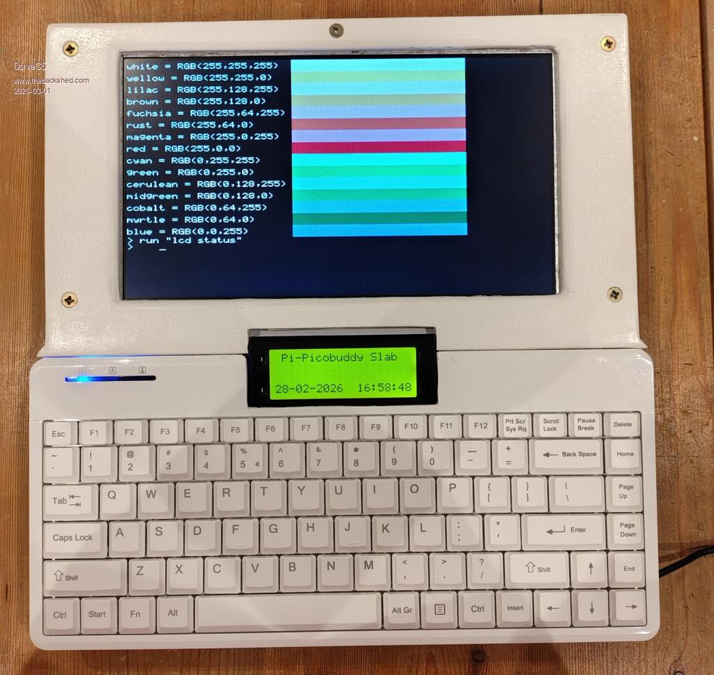
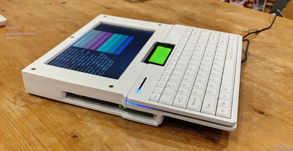
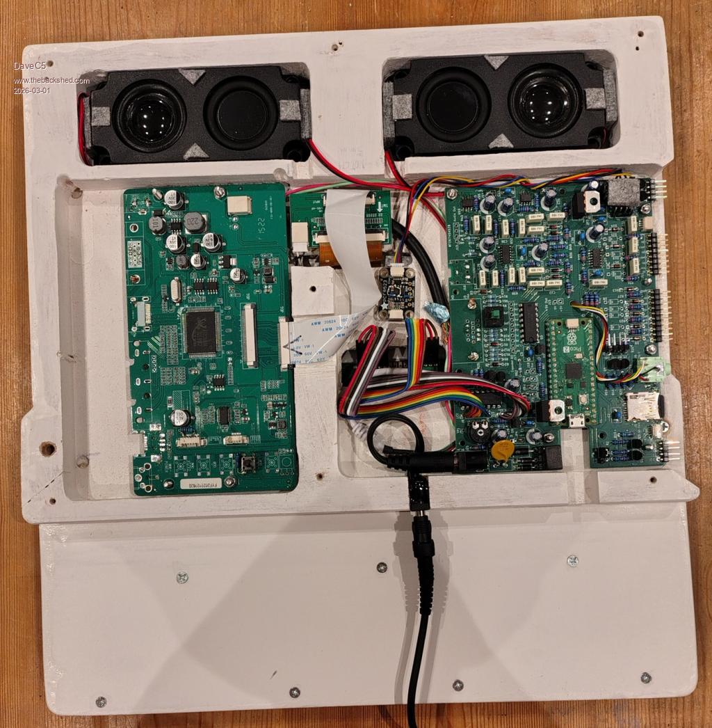
Super!!!

Edit:
Is this HDMI and what resolution(s) are possible?
Edited 2026-03-01 03:47 by dddns
 
Posted: 08:49pm
28 Feb 2026
Copy link to clipboard
phil99
Guru


In the photo of the internals both the Pi-Picobuddy PCB and the monitor PCB have a VGA socket footprint but I don't see a HDMI one on the Pi-Picobuddy.
https://www.thebackshed.com/forum/ViewTopic.php?TID=18321&PID
Edit.
From pcbway.com
  Quote  PicoBuddy Computer specifications

Based on the Raspberry Pi Pico 2040 microcontoller board running PicoMiteVGA Basic.
Official Raspberry Pi Pico 2350 boards have also been tested and provide greater memory, speed and display modes.
Powered supply options:
+5 V connected to the Pico USB connector
+5 V connected to the 2.1 mm barrel jack (reverse and over-voltage protection).
>5V connected to the 2.1 mm barrel jack (reverse and over-voltage protection) using onboard regulator.
Selection of onboard SMPS or linear regulators to optimise efficiency/noise
2 x I2C busses with STEMMA QT connectors and/or 4-pin headers. Each bus can be independently set to 5 V or 3.3 V operation
PS/2 keyboard input (USB available with the USB-enabled versions of the PicoMite Basic firmware)
Micro--SD card slot
5 x digital I/O
3 x buffered analogue-to-digital inputs, plus buffered 3.0 V reference supply
Stereo PWM output to headphones, or to 8 Ohm speakers via class A/B amplifiers
VGA output, two colour palettes
Onboard HD4487-compatible LCD interface
Onboard 8 x digital I/O

Edited 2026-03-01 07:09 by phil99
 
Posted: 07:17am
01 Mar 2026
Copy link to clipboard
DaveC5
Newbie

Hi,

It's just VGA. I have it set to 800x600, which is the native resolution of the LCDTV screen.


  dddns said  Super!!!

Edit:
Is this HDMI and what resolution(s) are possible?
 
Posted: 07:28am
01 Mar 2026
Copy link to clipboard
DaveC5
Newbie

Hi,

The LCDTV came with HDMI, VGA, BNC etc. interfaces, and the Pi-PicoBudddy only has a VGA output. To keep everything as compact as possible I removed all the unecessary connectors and hard-wired the necessary pins of the two VGA socket footprints together using a short length of cable salvaged from an old VGA lead, keeping individual screens etc. as intact as possible.

The slightly trickier bit was bodging on a "Source Selection" button so that the screen defaults to the VGA input, since I wasn't using the front-panel board from the LCDTV. It remembers the last setting, thankfully, but I've left the pushbutton as a recessed-access control just in case it ever forgets.


  phil99 said  In the photo of the internals both the Pi-Picobuddy PCB and the monitor PCB have a VGA socket footprint but I don't see a HDMI one on the Pi-Picobuddy.
https://www.thebackshed.com/forum/ViewTopic.php?TID=18321&PID
Edit.
From pcbway.com
  Quote  PicoBuddy Computer specifications

Based on the Raspberry Pi Pico 2040 microcontoller board running PicoMiteVGA Basic.
Official Raspberry Pi Pico 2350 boards have also been tested and provide greater memory, speed and display modes.
Powered supply options:
+5 V connected to the Pico USB connector
+5 V connected to the 2.1 mm barrel jack (reverse and over-voltage protection).
>5V connected to the 2.1 mm barrel jack (reverse and over-voltage protection) using onboard regulator.
Selection of onboard SMPS or linear regulators to optimise efficiency/noise
2 x I2C busses with STEMMA QT connectors and/or 4-pin headers. Each bus can be independently set to 5 V or 3.3 V operation
PS/2 keyboard input (USB available with the USB-enabled versions of the PicoMite Basic firmware)
Micro--SD card slot
5 x digital I/O
3 x buffered analogue-to-digital inputs, plus buffered 3.0 V reference supply
Stereo PWM output to headphones, or to 8 Ohm speakers via class A/B amplifiers
VGA output, two colour palettes
Onboard HD4487-compatible LCD interface
Onboard 8 x digital I/O
 
Posted: 07:30am
01 Mar 2026
Copy link to clipboard
DaveC5
Newbie

I should add that it's using the Pi 2 to get 800 x 600

Cheers

  DaveC5 said  Hi,

It's just VGA. I have it set to 800x600, which is the native resolution of the LCDTV screen.


  dddns said  Super!!!

Edit:
Is this HDMI and what resolution(s) are possible?
 
Posted: 08:53pm
01 Mar 2026
Copy link to clipboard
gadgetjack
Senior Member

Very nice project. Looks great!


To reply to this topic, you need to log in.

The Back Shed's forum code is written, and hosted, in Australia.
© JAQ Software 2026