Menu
JAQForum Ver 19.10.27

Forum Index : Microcontroller and PC projects : Enhancing Pi Pico Voltage measurement

Posted: 04:57am
01 Mar 2026
Copy link to clipboard
OA47
Guru


I want to get a Pi Pico to accurately measure voltages on an analog input. I have been using the attached input circuit to auto range by outputting a ground from a dig out pin to alter the voltage divider hence the range for the measured voltage.
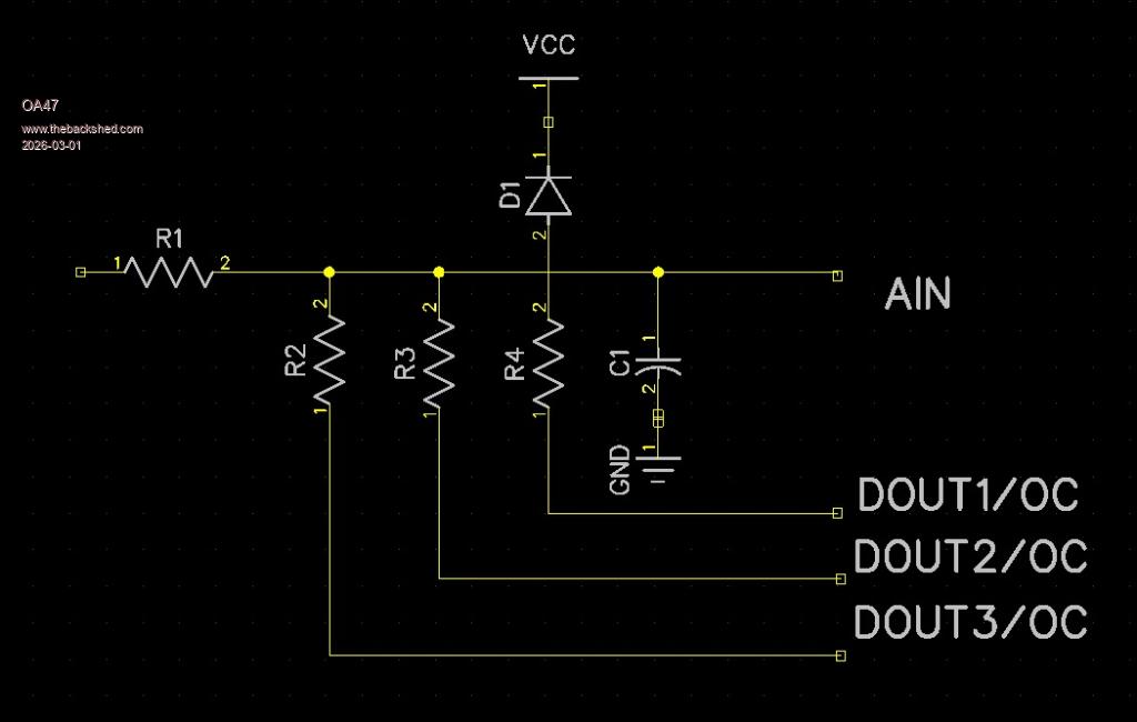


R1=1M0
R2=10K
R3=100K
R4=1M0 (R4 is always grounded)
D1=Schottky Diode

Here is a snippet of code I was using for the F4 ArmMite.


  ' Autoranging here
  Vm=Pin(PA0): Pause 100
  Volts=103.05*Vm                            'CALIBRATION EQUATION

  If Volts < 20 Then
   Pin(PA1)=1:Pin(PA2)=0                     '20V setting
   Vm=Pin(PA0): Pause 100
   Volts=12.05*Vm                            'CALIBRATION EQUATION
   BL=1:BEEP
  EndIf
  If Volts < 2 Then
   Pin(PA1)=1:Pin(PA02)=1                    '2V setting
  ' Pin(PA3)=0
   Vm=Pin(PA0): Pause 100
   Volts=2.05*Vm                             'CALIBRATION EQUATION
   BL=1:BEEP
  EndIf

  If Volts > 9.999 Then V$=Str$(Volts,2,2) Else V$=Str$(Volts,1,3)
  Text MM.HRes/2, MM.VRes/2 - 30,V$ , CM, 6, 2, RGB(white)
'  This code to emulate decimal point not available on first fonts
'   If Mid$(V$,2,1)="." Then Offset=95
'   If Mid$(V$,3,1)="." Then Offset=155
'   Circle Offset, 130, 6, 0, 1, 0, RGB(white)
  Text 150, 160, Date$, CM, 2, 1, RGB(Green)
  Text 150, 190, "UTC "+Time$, CM, 2, 1, RGB(Green)
  Offset=0

  DrawButton 0, 0, 0, 210, 90, 30, RGB(Red), "EXIT"
  DrawButton 1, 0, 110, 210, 100, 30, c.ghosttext, "HOLD"
  DrawButton 2, 0, MM.HRes-90, 210, 90, 30, c.ghosttext, "LOG V"
'   CheckButtonRelease btn
  If LogV=1 Then           'Log every 10 seconds
    If Right$(Time$,1)="0" Then Print "UTC,";Date$;",";Time$;",";V$
    Pause 800
  EndIf
  If LogV=2 Then           'Log every minute
    If Right$(Time$,2)="00" Then Print "UTC,";Date$;",";Time$;",";V$
    Pause 500
  EndIf
  If LogV=3 Then           'Log every hour
    If Right$(Time$,4)="0:00" Then Print "UTC,";Date$;",";Time$;",";V$
    Pause 500
  EndIf
 Loop
WatchDog 4000
End Sub


Can anyone help with suggestions to improve accuracy with the input circuit or the software?

OA47
 
Posted: 06:30am
01 Mar 2026
Copy link to clipboard
TassyJim
Guru


The Pico doesn't do Open collector DOUT.

Jim
 
Posted: 06:47am
01 Mar 2026
Copy link to clipboard
phil99
Guru


  Quote  The Pico doesn't do Open collector DOUT.
Yes, a bit annoying that.
In some situations you can simulate it with a diode, cathode to the pin (Schottky is best).

In this case the non-linearity of a diode would affect accuracy so you need to do it with SetPin commands.

PIN(x) = 0 : SETPIN x, DOUT 'switch to ground
SETPIN x, OFF 'open collector (drain)
 
Posted: 08:05am
01 Mar 2026
Copy link to clipboard
Mixtel90
Guru


You can simulate o/c DOUT without the non-linearity of diodes.

SETPIN GPx, DOUT
PIN(GPx)=0
SETPIN GPx, DIN

When you want the pin o/c use SETPIN GPx, DIN
When you want it pulled low use SETPIN GPx, DOUT

It will remember that as an output it will be low.

You are limited to a maximum of 3V6 on any GPIO pin though, so this is the maximum voltage you could measure.

Personally I'd put mosfets in the way and invert the outputs driving them. They need a pulldown resistor on the gate but small ones don't really need a gate series resistor from a GPIO pin. The on resistance is so low that it will have no effect and the off resistance is very high. The maximum voltage you can measure then is limited by the mosfet.


High value input resistors on the Pico ADC may not give good results. You may have to accept a lower potential divider value.
 
Posted: 08:08am
01 Mar 2026
Copy link to clipboard
DaveC5
Newbie

Hi,

To add to the points raised ...

Might those resistor values be a bit high? I think the input impedance of the RP2040 (for example) is around 100k, with a parasitic capacitance a few pF at least, so using 1M for the R1 input resistor might introduce a scaling error and also a low-pass filtering effect.

If this is causing a problem, a high-input-impedance buffer (J-FET input op-amp) between the output of this circuit and AIN on the Pi would help, as long as it's rail-rail I/O.

Can I ask, what sample rate are you looking at, and what would be the full voltage range?
 
Posted: 05:51pm
01 Mar 2026
Copy link to clipboard
Volhout
Guru

Hi OA47,

Not sure what the application is. In case of measuring a fixed voltage, you do not need switching attenuators. So I assume a digital voltmeter.
Not that with the shown circuit you can only measure DC volatges, and positive voltages only. So not very usefull.

When you use a RP2040 or a RP2350 stepping A4(the latest) you could switch between output low, and input modes of the GPIO pins. Not with the RP2350 stepping A2(the bulk of the RP2350's).

The only way to get this circuit accurate, is to "adjust" offset and gain in each range while using a calibrated digital meter in parallel. Simplest is to do a 10% and 90% measurement in each range.

If you want to create a digital multimeter that can measure positive, negative, and AC voltages, you need to create a negative voltage using a switchmode converter, and add a opamp between input and ADC. There are several circuits on the web that show you how to do this. With different attenuator settings, look at the analog input circuits of "Github SCOPPY". Google...is....your....best...friend

Volhout
Edited 2026-03-02 03:58 by Volhout


To reply to this topic, you need to log in.

The Back Shed's forum code is written, and hosted, in Australia.
© JAQ Software 2026