
| Menu | JAQForum Ver 19.10.27 |
| Menu | JAQForum Ver 19.10.27 |
Forum Index : Microcontroller and PC projects : 8 x 8 LED Matrix Editor
I'm using an 8 x 8 WS2182b square of LEDs in my robot project along with the LCD panel. I wanted an "easy" way to code images on the LEDs - so I used P5.JS as I'm familar with it and there are lots of resources on the web, and honestly AI is greate at javascript code. The editor is here: https://editor.p5js.org/gpg342/sketches/mVEqP2wxR It looks like this. Click on the "RUN" icon (top left) to activate it. 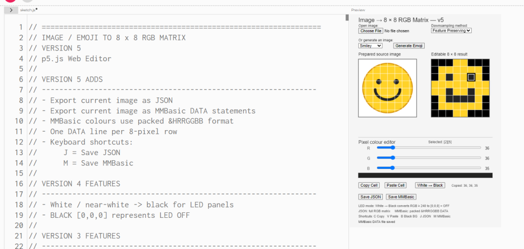 If you click on Save MMbasic - it will save out the image as 8x8 as data statements - ready to use in an MMBasic program. This produces an 8 x 8 image ready for me to use on the LED panel. It could of course be used to scale onto the LCD panel... 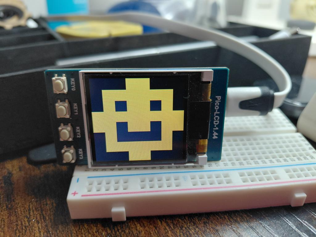 |
||||||
is this what you require? 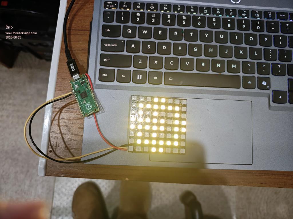 Option autorun on OPTION DEFAULT NONE OPTION EXPLICIT DIM integer loop1 diM integer LEDcolour1(64) SetPin GP5, DOUT do for loop1 = 0 to 63 read LEDcolour1(loop1) next loop1 senddata restore loop sub senddata Bitbang WS2812 B, GP5, 64, LEDcolour1() end sub Data &h000000,&h000000,&h000000,&h303000,&h303000,&h000000,&h000000,&h000000 Data &h000000,&h303000,&h303000,&h303000,&h303000,&h303000,&h303000,&h000000 Data &h000000,&h303000,&h000000,&h303000,&h303000,&h000000,&h303000,&h000000 Data &h303000,&h303000,&h303000,&h303000,&h303000,&h303000,&h303000,&h303000 Data &h303000,&h303000,&h000000,&h303000,&h303000,&h000000,&h303000,&h303000 ' Data &h000000,&h303000,&h000000,&h000000,&h000000,&h000000,&h303000,&h000000 Data &h000000,&h303000,&h303000,&h303000,&h303000,&h303000,&h303000,&h000000 Data &h000000,&h000000,&h000000,&h303000,&h303000,&h000000,&h000000,&h000000 . Bill Edited 2026-08-23 08:30 by Bill.b |
||||||
|
||||||
Left scroll ' Option autorun on OPTION DEFAULT NONE OPTION EXPLICIT DIM integer loop1,loop3,count2,loop2 diM integer LEDcolour1(80) diM integer Tempbuff(10) SetPin GP5, DOUT for loop1 = 0 to 191 next loop1 do for loop1 = 0 to 63 read LEDcolour1(loop1) next loop1 senddata restore Leftscoll1 loop sub Leftscoll1 for count2 = 0 to 23 senddata 'copy first row of leds into tempory buffer for loop3 = 0 to 8 tempbuff(loop3) = LEDcolour1(loop3) next loop3 for loop1 = 8 to 56 step 8 for loop2 = loop1 to loop1 + 8 LEDcolour1(loop2-8) = LEDcolour1(loop2) next loop2 PAUSE 10 next loop1 'load temproy buffer into last row of leds for loop3 = 0 to 8 LEDcolour1(loop3 + 56)= tempbuff(loop3) next loop3 pause 200 next count2 end sub sub senddata Bitbang WS2812 B, GP5, 64, LEDcolour1() end sub Data &h000000,&h000000,&h000000,&h303000,&h303000,&h000000,&h000000,&h000000 Data &h000000,&h303000,&h303000,&h303000,&h303000,&h303000,&h303000,&h000000 Data &h000000,&h303000,&h000000,&h000000,&h303000,&h000000,&h303000,&h000000 Data &h303000,&h303000,&h000000,&h303000,&h303000,&h303000,&h303000,&h303000 Data &h303000,&h303000,&h000000,&h303000,&h303000,&h303000,&h303000,&h303000 Data &h000000,&h303000,&h000000,&h000000,&h303000,&h000000,&h303000,&h000000 Data &h000000,&h303000,&h303000,&h303000,&h303000,&h303000,&h303000,&h000000 Data &h000000,&h000000,&h000000,&h303000,&h303000,&h000000,&h000000,&h000000 Bill |
||||||
I tried the example on an 8x8 matrix panel (type WS2812B-64). The first 14 RGB LEDs on the board light up. Apparently, there are two types, each with its own layout: one with a standard layout and one with a serpentine layout. With a standard layout: If we hold the 8x8 matrix in front of us with the connections (GND, +5V, DIN) at the bottom left: Then, in the standard version, LED 1 is at the bottom left and LED 8 is at the top left; LED 9 is at the bottom of the second column and LED 16 is at the top of the second column, and so on. With a serpentine layout: If we hold the 8x8 matrix in front of us with the connections (GND, +5V, DIN) at the bottom left: Then, in the serpentine layout, LED 1 is at the bottom left and LED 8 is at the top left; LED 9 is at the top of the second column and LED 16 is at the bottom of the second column, and so on. Or is there a third version? My connection pins at the bottom left are GND, DIN, and +3.3V to 5V, just like in the photo. The pattern matches the standard layout. Is it possible there is something wrong with my PCB? The colors on the first 14 LEDs work normally. Has anyone else had the same experience? Jan. |
||||||
I have had faulty 8 x 8 units supplied. if one LED is faulty the following LEDs will not function. Also I have used the alternate matrix this makes it difficult to do a shift right or left as you would need to invert each Columb of LEDs for each move. Bill |
||||||
@Jan We already have a thread where we discuss the WS2812 matrix. WS2812B LED with picoMite questions At the beginning, there are also very simple examples for testing all the LEDs. It doesn’t matter what layout you have. As Bill already pointed out, if one LED is defective, the ones that follow won’t work either. You could try replacing it or bypassing it. As far as I know, there are only two variants (column and serpentine layouts). Anything else wouldn’t make sense, in my opinion. @Nimue There's also an example where a BMP file is loaded. You can use any graphics program as the editor. Albert |
||||||
 |
The Back Shed's forum code is written, and hosted, in Australia. |


