Posted: 02:10pm 05 Jan 2022 Copy link to clipboard
Pluto Guru
Nokia 5110 is included in the firmware for PicoMite. I got it working on Picomite after some difficulties. Peter updated also the PicoMite firmware yesterday. THANKS.
In the past I used an old driver (anno 2014 by Peter) for standard Micromite (28-pin) successfully. When I recently tried to use that procedure on Micromite 5.0504, i run into difficulties.
Wondering now if there is any newer driver version for the standard MicroMite?
-fred
Posted: 06:10pm 05 Jan 2022 Copy link to clipboard
matherp Guru
There was a change in one of the MM versions that required a small change to all loadable drivers. Unfortunately I've lost the source for the 5110 driver so can't make the change. The only solution would be to use an earlier version of the MM firmware if you need this display - sorry
Posted: 08:45pm 05 Jan 2022 Copy link to clipboard
Pluto Guru
Thanks for checking. Got this code from 2015 working on Micromite 5.0504:
Initially I tried to change the ports used for rs, cdand cs for the SUB LCD.Init(rs,cd,cs,wi,ht,nr) w/o success. Going back to the ports originally used in the program was more fruitful.
LCD.Init 17,18,16
It will still leave some room for my own programs:
I believe that the stuff in library prevented me from chanching the rs, cd and cs pins!! -Fred
Posted: 05:23am 31 Jan 2026 Copy link to clipboard
WJSMarine Newbie
Hi Fred, I'm fumbling my way trying to get subject LCD to work on a PICO-W without success. I've had good success using 8bit PICs to do this task previously but new to MMBasic and the RP2040 environment.
Can I ask if you could share some of your PICO code to drive the Nokia lcd please? Just a snippet or two would be appreciated, I'm not asking for anyone to write my code, just a kickstart. I've had no problem with the other GLCD's, but the monochrome 5110 has me scratching my head. The only code I've found on TBS didn't help (MX170).
Many thanks, Bill (Perth, Australia)
Posted: 07:16am 31 Jan 2026 Copy link to clipboard
phil99 Guru
On Geoff's site latest firmware is MicroMite Firmware V5.05.05, 12/2021. It has a few useful extras.
Edit. I have a couple of Nokia 5110 phones in the junk box that may have usable displays but don't know how the 9 pads connect to the pins on the carrier board version. Does anyone have a circuit for the carrier board? Edited 2026-01-31 17:50 by phil99
Posted: 08:09am 31 Jan 2026 Copy link to clipboard
WJSMarine Newbie
Hi Phil, thanks for the response. I'm looking for PICO examples and it looks like Fred has his working, so would be my best shot at it. With the old Nokias you mention, do you mean the red eBay modules or the phone pcb itself? The red module I have has 8 pins (1 Rst, CE, DC, DIN, CLK, VCC, LED, GND). I can't help with the phone's pcb, unfortunately.
Cheers, Bill
Posted: 09:15am 31 Jan 2026 Copy link to clipboard
phil99 Guru
The phone itself. I need to map those 8 pins to the 9 pads on the LCD. If I can identify Vcc and Gnd I could use trial and error for the others without destroying it.
Posted: 09:48am 31 Jan 2026 Copy link to clipboard
matherp Guru
The 5110 is supported on the Pico-W. OPTION SYSTEM SPI then
manual page 63 I admit, this hasn't been tested recently, but it certainly used to work
Posted: 12:08pm 31 Jan 2026 Copy link to clipboard
Pluto Guru
I just connected a NOKIA 5110 LCD and tested with a standard PicoMite (green with Raspberry logo).
> option list PicoMite MMBasic RP2040 V6.02.00 OPTION SYSTEM SPI GP10,GP11,GP8 OPTION COLOURCODE ON OPTION CPUSPEED (KHz) 200000 OPTION LCDPANEL N5110, LANDSCAPE,GP13,GP14,GP15, 177
A few observations:
A. The LCD functions as "normal". B. Tried to use the INVERT mode: OPTION LCDPANEL N5110, OR, DC, RESET, CS [,contrast] [,INVERT] by setting the INVERT to 1. The display is not inverted. . Was my INVERT setting 1 correct?
C. When changing to invert mode I had to first set OPTION LCDPANEL DISABLE. After that the Pico is no more accessible. Tried to disconnect the LCD, but it did not help. Reloading the firware was required. Unexpected behaviour!
'Connection: 'PicoMite Nokia5110 'GP8 (MISO) Not connected. N5110 has no data out. 'GP10 (CLK) SCLK 'GP11 (MOSI) DIN(MOSI) 'GP13 (DC) D/C 'GP14 (RESET) RST 'GP15 (CS) SCE '3.3V VCC 'GND GND
Pluto
EDIT: Invert seems to be OK! Edited 2026-02-01 00:16 by Pluto
Posted: 07:54am 01 Feb 2026 Copy link to clipboard
WJSMarine Newbie
Hi folks, my problem was the default contrast at 177, when changed to 168 all was visible, doh!
@ Pluto, I tried setting invert (not accepted) and INVERT (accepted) but no change. Also tried as 1, accepted but still no change - can you give more info on how you achieved screen inversion please? Is it possible to invert only certain areas or characters? If so then so much more useful.
Also, CLS has no effect, I can only erase by writing spaces at the particular pixel locations - am I missing something here?
This is a very handy, if limited, LCD running off almost nothing. I'd be interested if any other TBS members have hints or features to share on these displays.
Kind regards, Bill
Posted: 08:33am 01 Feb 2026 Copy link to clipboard
matherp Guru
The INVERT parameter does not apply to the 5110. The manual needs correcting. To use white on black try COLOUR 0,1. CLS should work. If it doesn't try the command RERRESH after the CLS command. Let me know what happens.
Posted: 09:34am 01 Feb 2026 Copy link to clipboard
WJSMarine Newbie
Thanks Peter, put a star up against your name...
CLS does work, no idea why it didn't before. Inversion also works a treat and I expect with judicious placement I'll be able to invert small sections as required.
Thanks and regards, Bill
Posted: 09:47am 01 Feb 2026 Copy link to clipboard
Pluto Guru
When I have the LCD initialised with INVERT=1: CLS rgb(white) clears the screen and the screen is black. CLS rgb(black) clears the screen and the screen is white. text 0,0,"TESTING",LT,1,1,rgb(white),rgb(black) gives black text on white background.
=> THE SCREEN IS INVERTED. But option list does not show that INVERT is choosen.
. The display behaves now also exactly as described above for INVERT=1. Seems to me that the display is inverted regardless of what is set for the INVERT parameter (none or 1).
The display should be capable of both normal and inverse modes. Can it be that the E parameter is by mistake always at E=1?:
Edited 2026-02-01 20:33 by Pluto
Posted: 11:38am 01 Feb 2026 Copy link to clipboard
matherp Guru
This is the N5110 initialisation code for 6.02.00. INVERT is not implemented. It could be, but it isn't.
case N5110: ResetController(); spi_write_command(0x21); // LCD Extended Commands. uSec(20000); spi_write_command(Option.LCDVOP); // Set LCD Vop (Contrast). //0xB0 for 5V, 0XB1 for 3.3v, 0XBF if screen too dark uSec(20000); spi_write_command(0x04); // Set Temp coefficient. //0x04 uSec(20000); spi_write_command(0x14); // LCD bias mode 1:48. //0x13 or 0X14 uSec(20000); spi_write_command(0x20); // We must send 0x20 before modifying the display control mode uSec(20000); spi_write_command(0x0C); // Set display control, normal mode. 0x0D for inverse, 0x0C for normal uSec(20000); break;
Maybe your screen is wired differently. As I understand the post from WJSMarine. His screen is now working correctly using the colour command
Posted: 01:49pm 01 Feb 2026 Copy link to clipboard
mozzie Senior Member
G'day All, Peter, sorry to report it looks like Pluto may have stumbled on a bug. As he reported, if you use OPTION LCDPANEL RESET it: Resets the PicoMite Shows the startup banner No further interaction at the console is possible. Only re-downloading the firmware will fix it.
This is with N5110 and SSD1306SPI displays, haven't had time to test others.
PicoMite MMBasic RP2040 V6.00.02 is OK PicoMite MMBasic RP2040 V6.00.03 is NOT OK PicoMite MMBasic RP2040 V6.01.00 is NOT OK PicoMite MMBasic RP2040 V6.02.00 is NOT OK
Same option list with all versions
> option list PicoMite MMBasic RP2040 Edition V6.00.02 OPTION SYSTEM SPI GP2,GP3,GP4 OPTION COLOURCODE ON OPTION LCDPANEL N5110, LANDSCAPE,GP5,GP6,GP7, 177 >
Also a big thanks for all the work on V6.02.00, haven't yet had a chance for some further testing due to this mad fire season here in VIC AUS.
Regards, Lyle. Edited 2026-02-01 23:53 by mozzie
Posted: 02:15pm 01 Feb 2026 Copy link to clipboard
mozzie Senior Member
G'day WJSMarine, These displays are great for low power and daylight readable applications.
I use the following connections and settings: SCLK=GP2, DIN(MOSI)=GP3, D/C=GP5, RES=GP6, SCE=GP7 OPTION SYSTEM SPI GP2,GP3,GP4 OPTION LCDPANEL N5110,L,GP5,GP6,GP7
And this to test the display with the temp from a TMP36 sensor on GP28
' Program to display temps on N5110 Display ' TMP36 sensor on GP28 ' Deg C symbol is "(" in font 9
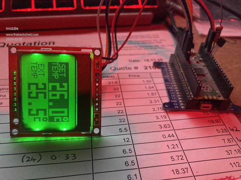
Do Settext For i = 1 To 5 Settemp Pause 1000 Next Box 0,0,28,24,,1,1 Text 3,4,"SET",,7,1,0,1 Text 0,12,"TEMP",,7,1,0,1 For i = 1 To 6 fgc=1:bgc=0 If i Mod 2 = 0 Then fgc=0:bgc=1 Text 28,0,Str$(20+i)+".0(",,9,1,fgc,bgc settemp Pause 1000 Next Loop while inkey$=""
Sub Settext Box 0,0,28,24,,0,0 Text 3,4,"CAB",,7,1 Text 0,12,"TEMP",,7,1 Text 3,52,"EXT",,7,1 Text 3,28,"EXT",,7,1 Text 0,36,"TEMP",,7,1 Text 28,0,"25.4(",,9,1 ' Text 28,24,"41.2(",,9,1 End Sub
Sub Settemp Ctmp$=Str$(100*(Pin(gp28)-0.5),2,1)+"(" Text 28,24,Ctmp$,,9,1 End Sub
And it looks like this when you change the backlight LEDS to green:
This font is designed to be easy for a blind old fart like me to read
Regards, Lyle. Edited 2026-02-02 00:27 by mozzie
Posted: 02:40pm 01 Feb 2026 Copy link to clipboard
mozzie Senior Member
G'day, A few more notes:
The units here have a RED PCB and there are a few issues with these LCD's: The PCB is too thin and warps away from the zebra strip, losing connection. The PCB is not gold plated and the connections for the zebra strip will tarnish, losing connection. The displays are either second hand / NOS or a second, I have a couple with odd pixels around the display area always black. (See previous post) A few have been dead on arrival but repairable, occasionally they cannot be revived
Good luck
Regards, Lyle.
Posted: 02:57pm 01 Feb 2026 Copy link to clipboard
matherp Guru
I assume you mean OPTION LCDPANEL DISABLE. I'll fix the issue but in the meantime you can probably use OPTION RESET to get rid of the N5110 (and everything else) then reload the other options
Posted: 12:31am 02 Feb 2026 Copy link to clipboard
WJSMarine Newbie
Hi Lyle, many thanks for sharing, the fog is lifting and it's good to see different ways of achieving a result.
Yes, great little displays and excellent for apps where mA's are precious, as most of my designs (predominately weather and ocean related), are. To date I've not had any issues with these displays from eBay using 12F/16F/18F PICs, but will be on the lookout now that you have mentioned it.
I'd just like to add here, that maestro Peter and Geoff have created an excellent platform and it is obvious there are countless hours invested to get this far and continue into the future with further development. A very big THANK YOU to both and other, long-established contributors for keeping the ball rolling.
Kind regards, Bill
Page 1 of 2
The Back Shed's forum code is written, and hosted, in Australia.

 Going back to the ports originally used in the program was more fruitful.