| Menu | JAQForum Ver 19.10.27 |
| Menu | JAQForum Ver 19.10.27 |
Forum Index : Microcontroller and PC projects : 2040 2350 and diy
| Page 1 of 3 |
||||||
lot of discussion lately. I was going to post an easy vero board but it's soldering and not fun if you want compact... like olimex, which was sold for 2040 but is hdmi board? works ok ish with 2350 mmbasic hdmi. so 2040 can do hdmi? is there anything else like olimex no soldering needed? |
||||||
The only way I can think of to get something like that is modules plugged into a breadboard with wire links. It's not easy to have a completely no solder system as even most of the modules need the header pins soldering before you can use them. |
||||||
I'll use the pins supplied as solder wiring avi messed it. ordered 2 more pihut then found I had a spare. can't find coloured wire. |
||||||
For cheap coloured 30AWG wire get a mixed roll of 8 colours of wire-wrap wire. AliExpress £4.29 for 250m. Alternatively, Bitsbox do 5m lengths of Kynar in blue, red, green, yellow and black for £1.20 per length. 5m doesn't sound a lot but it goes quite a long way on a PCB. :) |
||||||
I got some "somewhere". I tried some old pc ribbon for connecting old drives all grey but holes on dvi board bit small and messed up. tried molex coloured cable used for bread boarding and cut off the male/female connector to find how poor the wire was. it's poor without the r. as I look through boxes searching for something I found lots of electronics I'd forgotten I had :) stan |
||||||
Just stick an order in to Bitsbox for some Kynar or one of their wire packs. They are pretty quick, their stuff is good and postage is fixed price and reasonable (£2.50 per order). Don't mess with rubbish. :) . Edited 2025-06-12 02:20 by Mixtel90 |
||||||
You can get a massive 50m drum of alarm wire from screwfix - link Strip it and use it for hook up wire. Dave. |
||||||
ok the first try which I tested with molex type male to female, The idea was wires under the board but just testing and isn't it amazing you can use molex like this to test and it works. bubble universe running 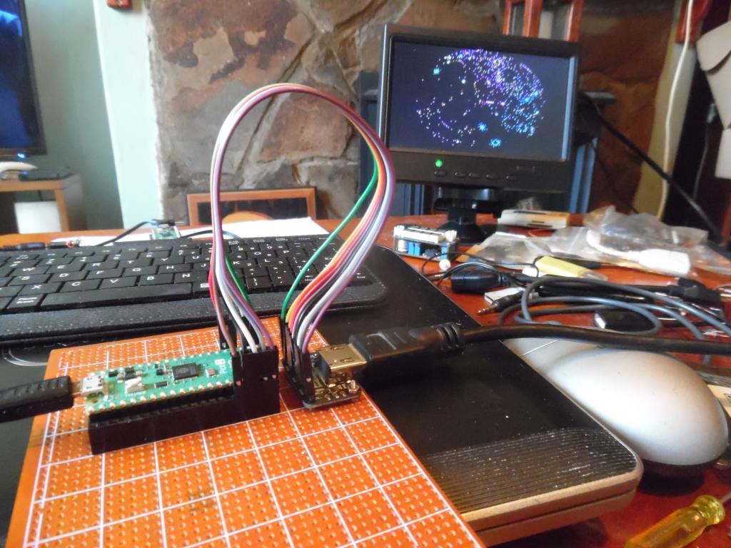 it's not a bad dvi board Mick. I just want more people to use mmbhasic but not get cocky or it get rocky |
||||||
it looks tidier than before but not fun wiring/ add usb to ttl and sd card reader next. no joining links between strip board tracks yet. 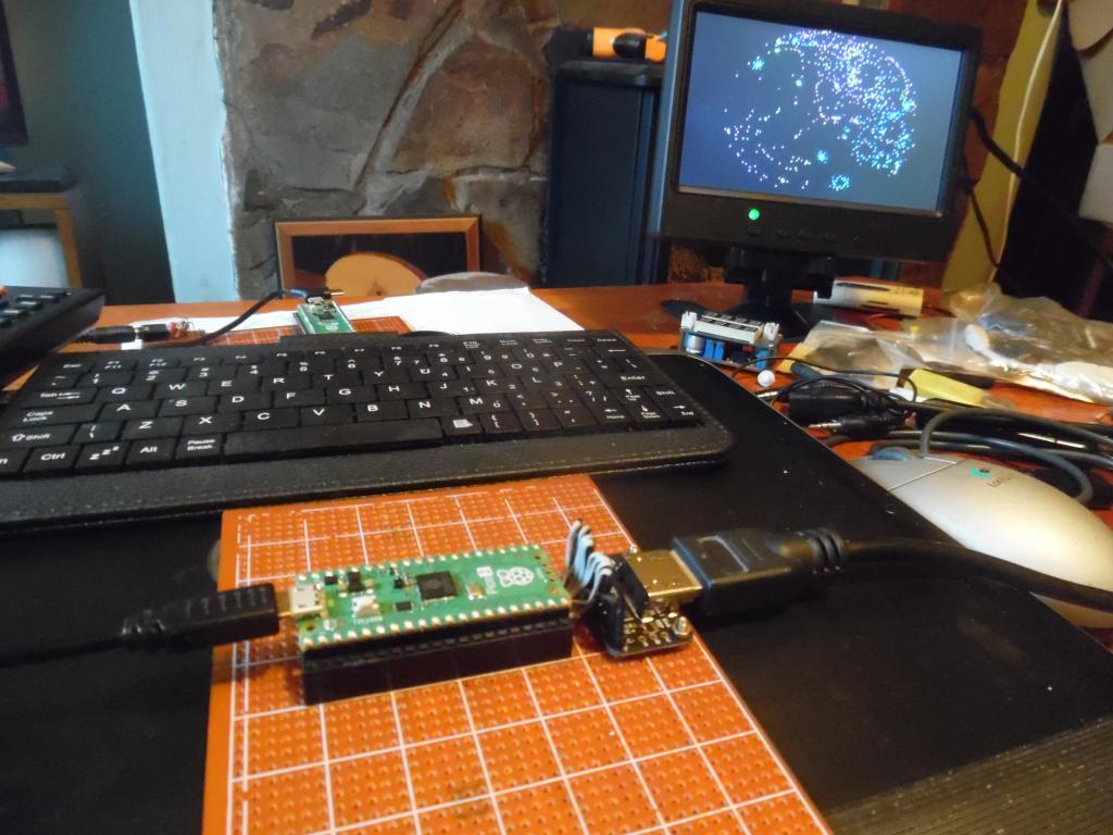 |
||||||
a point is hdmi isn't as fussy as some say. this is first try at using flying leads and the leads from dvi to gp pins I haven't have not cut all the extra unused tracks and the capacitance between them yet. using ribbon cable is capacitance between leads but is common. maybe it's accounted for |
||||||
To know if it's ok you have to run the HDMI at the highest speeds, not necessarily the ones that that monitor can handle. In other words, you need a known good design to see what the maximum speed is that your monitor will work with then test it using the knitted wires system. Even then, unless you reached the top speed you can't really say that the rats nest works properly. |
||||||
is there a test program other than change resolution and draw filled circles in different modes? other peoples code gives heap error often |
||||||
I flashed the hdmi usb and temp wired a usb c to ttl and used the 5V to power pico pin 40 vbus. I got a usb keyboard connected that's uk but always start with mum lock on and always types daft chars. got to do the micro sd card next to get "the complete kit :(" 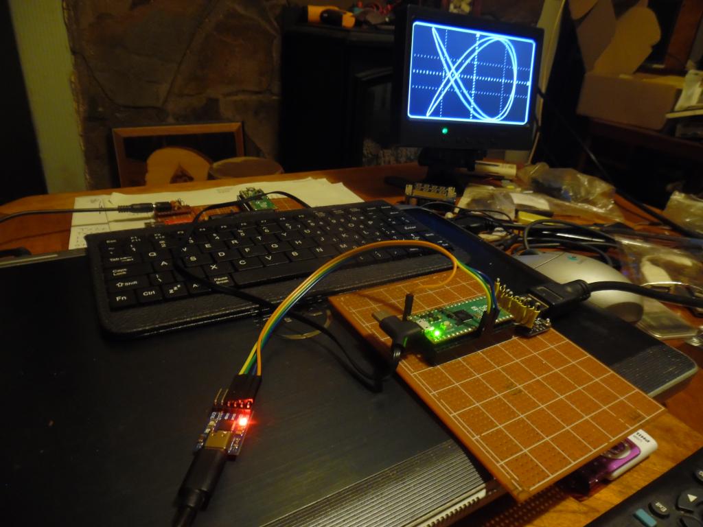 got a few sd card readers, latest 3V so use pico 3.3V out or usb to ttl 3v out? just the layout as want it all rats nest wiring and no links between tracks as never tried before |
||||||
OPTION KEYBOARD UK |
||||||
SD card sockets can't have the built in level shifters. They convert the signals to 5V, which is no use for the Pico. They are usually sold as being for the Arduino. SD cards are all 3V3 and the Pico needs a direct connection. Avoid any card modules with components on them with one exception that I know of. That one is the one I call the "inverted" module because it always used to be sold with ready soldered pins on the same side as the socket, although you can get it without the pins now. That one has decoupling capacitors and pullup resistors on it but it works very well indeed. |
||||||
This an existing board with large sd card and adaptor.. like ili9341 uses large card and I use a micro sd card adaptor. > option list PicoMiteHDMI MMBasic USB RP2350A Edition V6.00.02b0 OPTION SERIAL CONSOLE COM2,GP8,GP9 OPTION AUTORUN ON OPTION FLASH SIZE 4194304 OPTION COLOURCODE ON OPTION KEYBOARD UK OPTION CPUSPEED (KHz) 315000 OPTION SDCARD GP22, GP6, GP7, GP4 OPTION AUDIO GP0,GP1', ON PWM CHANNEL 0 > this is the "new" one, no sd card option yet. option list PicoMiteHDMI MMBasic USB RP2350A Edition V6.00.02RC24 OPTION SERIAL CONSOLE COM2,GP8,GP9 OPTION FLASH SIZE 4194304 OPTION COLOURCODE ON OPTION KEYBOARD UK OPTION RESOLUTION 640x480 @ 252000KHz > 2 sd card readers, one looks passive and meeds 3.3V, the other looks like it got a reg so probably needs 5V never had problems with sd card readers before. used the manual suggested settings 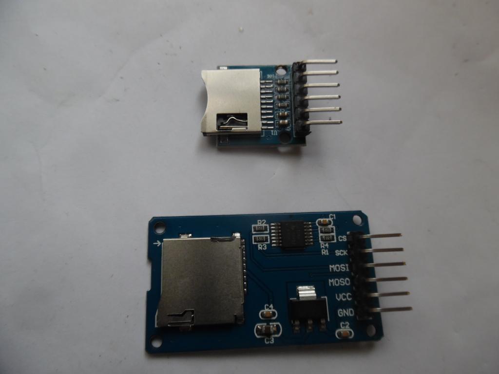 |
||||||
As long as it has a AMS1117 low drop you can try any card by powering it with 3V3. Haven't had a sdcard problem even not with 15 years old ones as most have anyway a separate 3V3 input. The 2350 takes 5V at most pins.. Edited 2025-06-14 03:57 by dddns |
||||||
looking in the manual is this correct please? card pins gnd miso-----GP4 clk------GP6 mosi-----GP7 cs-------GP22 3v3--- from pico or usb to ttl then use OPTION SDCARD GP22,GP6,GP7,GP4 haven't tried cos only 6 wires I could mess up. 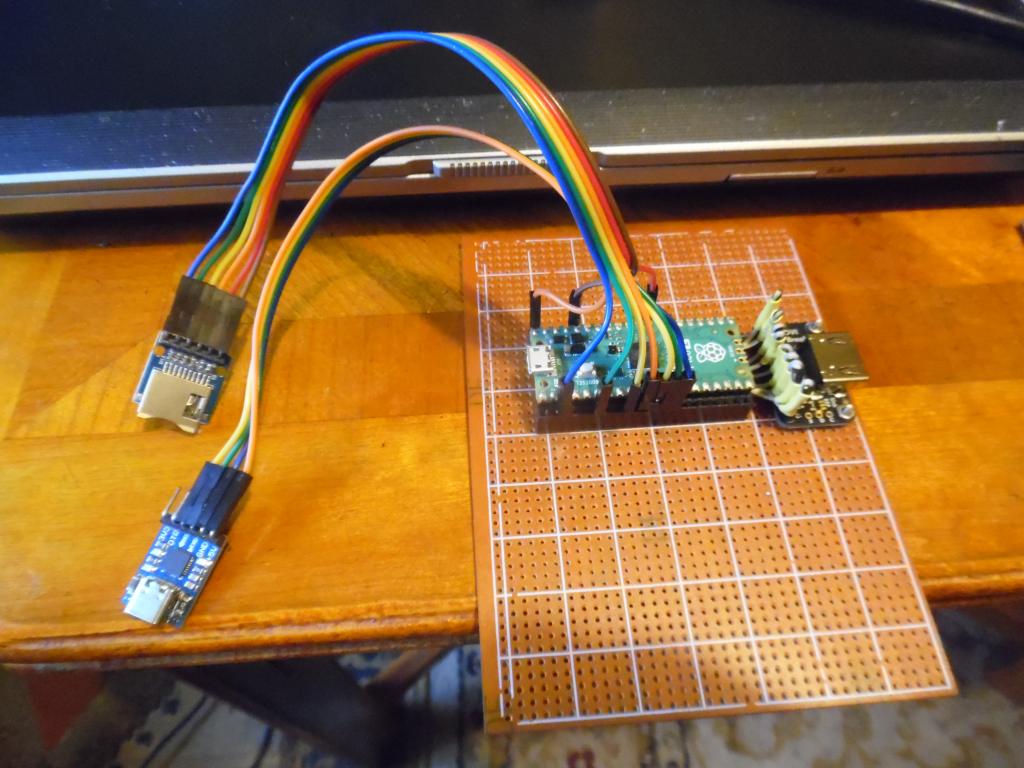 |
||||||
The top module will work. The bottom one might work, might not or might be touch and go, depending. :) It's intended for a 5V supply. The voltage regulator won't regulate if you power it at 3V3 (not enough voltage across it) and the level shifter might be marginal because of that. All SD cards are 3V3. They work fine when fed from the Pico. You can probably use the socket in the bottom picture by powering it from 5V rather than 3V3. Take the supply from VSYS. For testing purposes you can use any GPIO pins for a SD card providing you specify them all in OPTION SDCARD. . Edited 2025-06-14 04:54 by Mixtel90 |
||||||
got this from passive card reader so think it's ok... now to wire it as all this was test wiring then audio out, yawn files A:/ <DIR> . <DIR> .. 00:00 01-01-2024 4 bootcount 2 directories, 1 file, 2527232 bytes free > b: > files B:/ 19:05 28-07-2020 8802830 adele,tupac,eminem.mp3 21:07 29-09-2024 67081508 adele,tupac,eminem.wav 17:38 28-07-2020 8444268 Biggie,Adele,Tupac.mp3 21:08 29-09-2024 65642084 Biggie,Adele,Tupac.wav 22:16 28-07-2020 5338459 biggie.johnny cash.mp3 21:08 29-09-2024 39577644 biggie.johnny cash.wav 22:54 23-09-2024 138982 fatlib.bmp 16:48 30-08-2024 44556 sfx-bg.mod 20:35 20-03-2020 49501189 THENOT~1.MP3 21:11 29-09-2024 363818330 THENOT~1.WAV 18:49 28-07-2020 7598885 tupac,eminem.mp3 21:11 29-09-2024 54718580 tupac,eminem.wav 0 directories, 12 files this was with "the top one" Mick but I gonna try the 5 V? card cos I used them dim problemo... just to test. it was initially an easy diy plan but take it back it's not easy. soldering is worse than smoking Edited 2025-06-14 05:40 by stanleyella |
||||||
| Page 1 of 3 |
||||||
| The Back Shed's forum code is written, and hosted, in Australia. |
