Menu
JAQForum Ver 19.10.27

Forum Index : Microcontroller and PC projects : R-2R DAC + OpAMP -- advice needed

Posted: 04:00pm
13 Jun 2025
Copy link to clipboard
Nimue
Guru


Hi

My circuit-fu is very rusty here and I long ago lost my "Horotwitz and Hill" -- any good contemporary books?  (H&H is still £60+ and 2016)

Problem:
I have a 4 bit DAC via a resistor ladder - works as expected.
I now need shift it to cover the range 1.2V to 4V not 0V-3(ish)V

My thinking is (maths)..

Vout = a x Vin + b   -- where a is the scaling and b is the offset.

When Vin is 0 => 0a+b = 1.2
When Vin is 3 => 3a+b = 4

Solving - gives a as 0.9 and b as desired 1.2.

Now I'm into the world of op Amps - summing, non-inverting etc etc.  Arrrghh!

Two Stages
Stage 1: scale
Stage 2: add the offset.

At this point my head hurts.

I know there are single chip solutions for this (gain+offset) like the AD633 but they are far to cost prohibitive for this (ie £10 each in small numbers).

What's the best way shift my 0-3.3V output to 1.2 to 4V?  And by "best" I mean easiest for me to get my brain around.
 
Posted: 04:41pm
13 Jun 2025
Copy link to clipboard
Nimue
Guru


From the TI sheets on OpAmps:


All in one stage....


Seems clear enough - except Vref -- I am assuming this is my 1.2V....

N
Edited 2025-06-14 02:41 by Nimue
 
Posted: 04:44pm
13 Jun 2025
Copy link to clipboard
PhenixRising
Guru

PWM and a LM358? Lots of examples out there.
 
Posted: 04:51pm
13 Jun 2025
Copy link to clipboard
Nimue
Guru


  PhenixRising said  PWM and a LM358? Lots of examples out there.


I thought PWM didn't actually vary the voltage, just switch it very fast in a duty cycle?  LEDs for example just flash very quickly, which looks like they are experiencing different voltage but the instantaneous voltage is still the same?

Otherwise wouldn't we use that to generate the voltage for VGA?

Happy to be wrong though - as said, been a long time.....
 
Posted: 06:46pm
13 Jun 2025
Copy link to clipboard
Mixtel90
Guru


PWM has a constant frequency bu changes the mark/space ratio of the output square wave. The trick is to filter the output to extract this change in mark/space ratio as a DC voltage. The filter can be as simple as a resistor and a capacitor. Using this method you can't actually get 0% and 100% output as these would be steady voltages, but you can get very close. The values for the filter are a compromise between how much of the PWM frequency you want to get rid of and how fast the output voltage changes when the mark/space ratio is changed.

Basically, PWM is a poor man's D-A converter, but it works very well. You can get virtually zero to not far off 3V3 out of a single pin on a Pico. Handy for all sorts of DC voltage control.

The Pico can also use it for PWM audio, using a PWM frequency of about 40kHz.

The op-amp circuit will work fine. Vref is added to or subtracted from Vin at the op-amp input. Rf and Rg set the gain applied to that input.

If you want to get down to low voltages then you will probably need both positive and negative supplies to the op-amp. If you don't then you may find that the op-amp's offset voltage gives you an error on the output. Also, try not to expect the output to reach the positive rail. Try to run it from +/- 6V or something like that if you want 4V, You might get away with +5V and just a couple of volts on the negative rail. You could get that from a negative diode pump driven from a PWM pin. :) Or a 1.5V battery...  Not all op-amps are equal and some will be better than others for this. Rail to rail op-amps may even work happily from 5V to give the output that you want.
 
Posted: 07:28pm
13 Jun 2025
Copy link to clipboard
PhenixRising
Guru

@Nimue

Are we still on with the solenoid, by chance?

If so, simply select a device that can provide the current and hit it with PWM.

I do it all the time and have $150 hydraulic valves instead of $2,500 proportional valves working perfectly.
 
Posted: 07:28pm
13 Jun 2025
Copy link to clipboard
Nimue
Guru


  Mixtel90 said  The trick is to filter the output to extract this change in mark/space ratio as a DC voltage. The filter can be as simple as a resistor and a capacitor. Using this method you can't actually get 0% and 100% output as these would be steady voltages, but you can get very close.


^^ Nice - didn't appreciate this "trick" until you spelled it out.

The voltages wont be changing quickly from the DAC - maybe changing every couple of seconds so plenty time to stabalise.  

Got plenty of electrlytics and a bag  of 100nF / 50nf ceramic.  Am guessing that ceramics are best in this case.

Thanks for the pointer.
 
Posted: 07:37pm
13 Jun 2025
Copy link to clipboard
Nimue
Guru


  PhenixRising said  @Nimue

Are we still on with the solenoid, by chance?

If so, simply select a device that can provide the current and hit it with PWM.

I do it all the time and have $150 hydraulic valves instead of $2,500 proportional valves working perfectly.


We're not - but..... now you mention it.

This is for the question related to LEDs.

What I am doing is ramping up the voltage across an LED until it just lights (actually until 0.5mA flows (sense resistor) ) and then recording the voltage it took to drive that.

I have a light spectrometer (nice kit) and measure the light frequency from various LEDs. From this and the voltage it takes to "strike" an LED you can calculate Planck's constant.  Measure the voltage for a range of LED colours, plot a graph and calculate Planck's constant.  If you do this by eye (ie when an LED just turns on) - you can get to within 10% of Plank.  Designing this - hope to get to with 5%.

(This is for post-16 learners doing A-level physics).
 
Posted: 07:02pm
15 Jun 2025
Copy link to clipboard
Volhout
Guru

Hi Nimue,

Sorry for my late reply.
To drive your LED during the tests, I suggest you use a pico PWM output.
When you run the PWM at 1kHz (at 63MHz PWM time frequency) you get near 16 bit resolution. 16 bit PWM resolution is more that you would achieve in an R-2R ladder network due to tolerances in resistors in the R-2R network, and it is far simpler.

Since the PWM  has the amplitude of 0 to VCC (around 3V3 on a pico) you need to amplify the 3.3V PWM signal to get your desired 4.4V highest level.

You are suggesting to match the 0-3.3V exactly towards the desired output voltage range, but that would not be my suggestion. Since the 3.3V on your particular pico board may be 2-3% lower or higher (talerances in the power supply chip) I suggest to use at least 5% overhead, and calibrate the output voltages in software (using a accurate voltmeter).

In that case I suggest to make the circuit very simple, like below. That gives an output range of 0V...5V (in fact it will be 0.03V...4,95V). That covers your needs.
The output should be 1.2V at a PWM of 24% and 4.4V at a PWM of 88%.


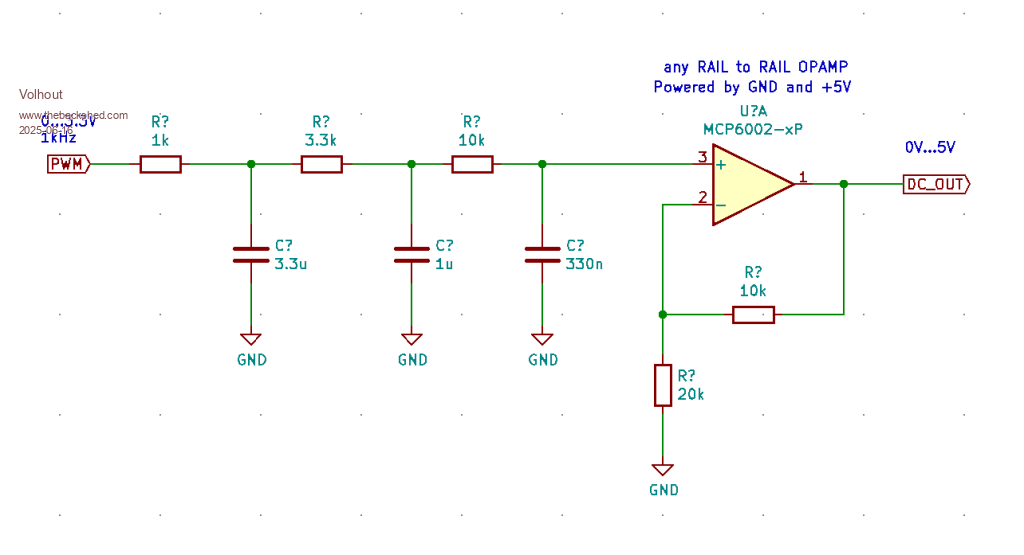
The opamp can be any rail-rail opamp. Look what you have in your toolbox.

Good luck building the tester

Volhout

P.S. you can also use a cheap LM358, but only of you power the opamp from 7V (the LM358 cannot output 5V when powered from 5V).
Edited 2025-06-16 05:08 by Volhout


To reply to this topic, you need to log in.

The Back Shed's forum code is written, and hosted, in Australia.
© JAQ Software 2025