| Menu | JAQForum Ver 19.10.27 |
| Menu | JAQForum Ver 19.10.27 |
Forum Index : Microcontroller and PC projects : The ILI9341 display rotates the coordinates.
| Page 1 of 2 |
||||||
My new project, "Human Radar" (https://www.thebackshed.com/forum/ViewTopic.php?FID=16&TID=18438), uses a 320x240 ILI9341 display. With these options: PicoMite MMBasic RP2040 Edition V6.00.03 OPTION SYSTEM SPI GP6, GP3, GP4 OPTION AUTORUN ON OPTION COLOURCODE ON OPTION CPUSPEED (KHz) 200000 OPTION LCDPANEL ILI9341, LANDSCAPE, GP7, GP2, GP5 everything works perfectly. 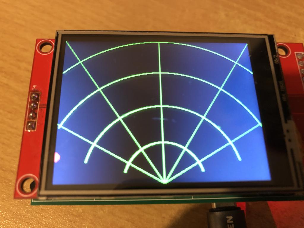 Now I've bought four more displays from AliExpress, which also use the ILI9341 display driver. They look like the display I'm currently using. However, it appears they're using portrait mode, even though landscape is selected. The small red dot on the left side of the display in the radar grid isn't red, as it should be, but blue. 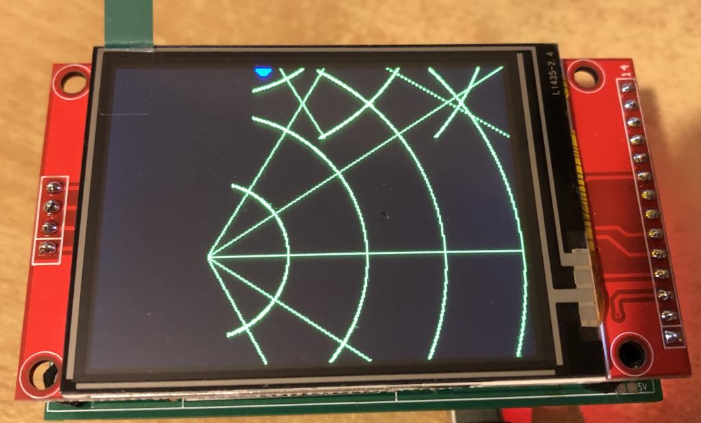 I've tried all the available settings for the ILI9341 (L, P, RL, RP). The display rotates, but it's not using the full 320 x 240 pixels. It looks like it's using 0-240 for X and 0-320 for Y. Does anyone have any suggestions on how I can use this display with a different setting? |
||||||
Backside of the "good" ones. 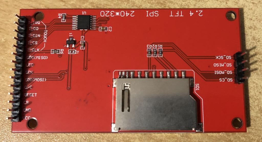 Backside of the "bad" ones. 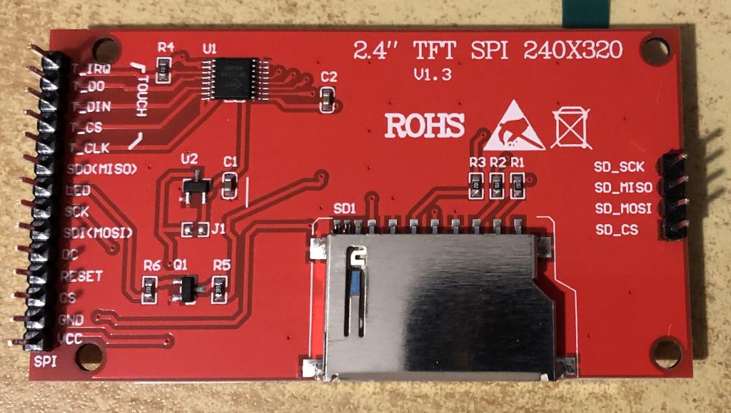 Edited 2025-12-05 08:41 by v.lenzer |
||||||
The Red/Blue reversal should be fixed by using the INVERT parameter when the display is setup. OPTION LCDPANEL .................,INVERT You can adjust the driver setting after it initiates using POKE DISPLAY command [,data1] command &H36 is the likely area you need to adjust. e.g. POKE DISPLAY &H36,xx This from the source might help help working out how to swap Landscape/Portrait after it is loaded. #define ILI9341_MEMCONTROL 0x36 #define ILI9341_MADCTL_MY 0x80 #define ILI9341_MADCTL_MX 0x40 #define ILI9341_MADCTL_MV 0x20 #define ILI9341_MADCTL_ML 0x10 #define ILI9341_MADCTL_RGB 0x00 #define ILI9341_MADCTL_BGR 0x08 #define ILI9341_MADCTL_MH 0x04 // ILI9341 Orientation Modes #define ILI9341_Portrait (ILI9341_MADCTL_MX | ILI9341_MADCTL_BGR) #define ILI9341_Portrait180 (ILI9341_MADCTL_MY | ILI9341_MADCTL_BGR) #define ILI9341_Landscape (ILI9341_MADCTL_MV | ILI9341_MADCTL_BGR) #define ILI9341_Landscape180 (ILI9341_MADCTL_MY | ILI9341_MADCTL_MX | ILI9341_MADCTL_MV | ILI9341_MADCTL_BGR) |
||||||
Hi Joachim, Once you defined the correct settings, could you please share these. I also have some 2.4" on order, and fear the same issue. Thank you Volhout |
||||||
Thank you for the information. I managed to make the display now look the same as the other displays. When setting the option for the LCD, I entered "RP" as the orientation and in the program poke display hres 320 poke display vres 240 When I want to append "INVERT" to the LCD OPTION, I get an error (PIN 0/NULL). It worked with a fantasy GPIO, but all colors were inverted. The blue dot became yellow and the actually correct green lines were also inverted. But you can set that with LINE and CIRCLE. That's not a problem. 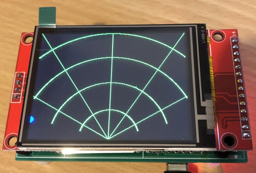 PicoMite MMBasic RP2040 Edition V6.00.03 OPTION SYSTEM SPI GP6,GP3,GP4 OPTION COLOURCODE ON OPTION CPUSPEED (KHz) 200000 OPTION LCDPANEL ILI9341, RPORTRAIT,GP7,GP2,GP5 Edited 2025-12-05 22:53 by v.lenzer |
||||||
The first optional parameter is a pin for the backlight. The second is the invert option. Just use ,,INVERT HOWEVER invert won't do what you want as it makes black white. Try using bit 3 in register &H36 #define ILI9341_MADCTL_BGR 0x08 |
||||||
I found this type of color errors typically on IPS displays and the INVERT parameter cured it. Had this also when I retrofitted a TFT display with an IPS panel. Gerald |
||||||
As in my reply above, invert is different to a simple B/R swap.IPS displays without invert set see a value of 0 as full on and 255 is off for each of R G and B. The OP is not seeing an inverted display just a R B swap. The control for this in a ILI9341 is bit 3 of register &H36 |
||||||
I must confess that I don't quite understand what I'm supposed to try. I can't make heads or tails of `#define`. I'm more of an assembly language person. I'm programming the RP2040 using MMEdit and I am trying to understand MMBasic in this way. If you could tell me what to enter, either on the console or in MMEdit, that would be a huge help. I'm sure we can get somewhere that way. It would be good for the future, since there are obviously other ILI9341 displays out there that are different. And indeed, INVERT inverts all colors. In my case, the black background becomes white, the green mesh is somehow pink, and the dot is yellow. I was able to enter the inverted LCD option with two commas. I hadn't thought of that. Edited 2025-12-06 07:43 by v.lenzer |
||||||
So "RP" is now setting &H36 as 0x88 , if we don't want Bit3 then try POKE DISPLAY &H36,0x80 or POKE DISPLAY &H36,0x88 if we have it the wrong way. and then your poke display hres 320 poke display vres 240 |
||||||
Following a tip I found online that AliExpress was selling displays with the wrong driver (for example here https://lecity.edu.au/?p=2761), I entered this option: `OPTION LCDPANEL ST7789, LANDSCAPE,GP7,GP2,GP5,,INVERT`. Now all the colors are correct! Together with `poke display hres 320` and `poke display vres 240`, the orientation is also correct. Edited 2025-12-06 08:31 by v.lenzer |
||||||
A bit of trial and error using the information from Peter and disco4now was able to swap red and blue on a normal ILI9341. However this also created the same problem you had with vertical and horizontal. Using your cure for that restored things. Give this a try. > poke display &H36, &H03 > cls rgb(blue) > cls rgb(red) > poke display hres 320 > poke display vres 240 > cls rgb(blue) > cls rgb(red) > poke display hres 240 > poke display vres 320 > cls rgb(blue) > cls rgb(red) > PS. Poke Display &H36, &H00 returned the display to original settings. Edited 2025-12-06 08:28 by phil99 |
||||||
Thank you so much for your message, phil99! That's helpful. My options: > option list PicoMite MMBasic RP2040 Edition V6.00.03 OPTION SYSTEM SPI GP6,GP3,GP4 OPTION COLOURCODE ON OPTION CPUSPEED (KHz) 200000 OPTION LCDPANEL ILI9341, RPORTRAIT,GP7,GP2,GP5 I tested with these lines: poke display &H36, &H03 cls rgb(blue) cls rgb(red) poke display hres 320 poke display vres 240 This solved the color problem. BUT: now X0/Y0 is no longer in the upper left corner, but in the upper right corner. I don't understand it, but that's how it is. This is the entire program. Please note that this was only intended to help understanding the graphics commands. It has nothing to do with the radar program. I think there's a simpler way to convert from polar coordinates to Cartesian coordinates. ... 'Hires tests 'Display of the display and font parameters 'print "Vertical resolution :";mm.vres 'print "Horizontal resolution :";mm.hres 'print "Font height :";mm.info(fontheight) 'print "Font width ;";mm.info(fontwidth) ' 'Drawing commands: 'poke display hres 320 'poke display vres 240 poke display &H36, &H03 cls rgb(blue) cls rgb(red) poke display hres 320 poke display vres 240 'cls rgb(blue) 'cls rgb(red) 'poke display hres 240 'poke display vres 320 'cls rgb(blue) 'cls rgb(red) midx=160' x-center midy=240 'y-center netr=50' element length arc radius startw=22.5' start angle arcw=135' arc angle for i=0 to 90 radar_net r=200 w=i w=(w*pi)/180 x2=r*cos(w) y2=r*sin(w) 'print "X2:"x2;" Y2:";y2;" W:";w circle x2,y2,6,,1,rgb(red),rgb(red) break 100 next i end sub radar_net cls arc 160,240,60,,285,75,rgb(green) arc 160,240,120,,285,75,rgb(green) arc 160,240,180,,298,62,rgb(green) arc 160,240,240,,318,42,rgb(green) line 0,0,160,240,,rgb(green) line 160,0,160,240,,rgb(green) line 320,0,160,240,,rgb(green) line 0,150,160,240,,rgb(green) line 320,150,160,240,,rgb(green) end sub It is now after midnight in Germany. All I can see before my burning eyes is "OPTION LCDPANEL DISABLE". I'll continue tomorrow :) Edited 2025-12-06 09:25 by v.lenzer |
||||||
I think that you need POKE DISPLAY &H36,0x80 It is bit 3 (decimal 8) not decimal 3 and you need bit 3 set to 0 leaving the other bits set as required for display orientation. Jim |
||||||
More testing. OPTION LCDPANEL ILI9341, RLANDSCAPE,....... and POKE DISPLAY &H36, &H20 Swapped red and blue with pixel (0,0) at top left and (320,240) at bottom right so Hres and Vres are correct. SD card is at the bottom. POKE DISPLAY &H36, &H60 Swapped red and blue with pixel (0,0) at bottom left and (320,240) at top right so Hres and Vres are correct. SD card is at the bottom. POKE DISPLAY &H36, &HA0 Swapped red and blue with pixel (0,0) at top right and (320,240) at bottom left so Hres and Vres are correct. SD card is at the bottom. POKE DISPLAY &H36, &HE0 Swapped red and blue with pixel (0,0) at bottom right and (320,240) at top left so Hres and Vres are correct. SD card is at the bottom. If using OPTION LCDPANEL ILI9341, LANDSCAPE,....... they would all be reversed. |
||||||
I think the mystery is solved: I got displays with the ST7789 from Aliexpress. If you look at the pictures of this Offer or here in this post , then you can see what the ST7789 displays look like on the back. And I have one exactly like that. I'll continue to try out your suggestions later today. Maybe a good solution will be found so that I or a future colleague can still use this display. |
||||||
If it is a st7789 then use OPTION LCDPANEL ST7789_320,L,... This properly configures a st7789 in 320x240. Then, if necessary you can tweak from there |
||||||
The next problem: The display cannot be calibrated as an ILI9341. The calibration crosses on the portrait screen are not at all four corners, but rather twice at the top left and top right. Let's see what the setting changes bring. This was the error message: Warning: Inaccurate calibration Deviation X = 0, Y = 342 (pixels) As ST7789 in connection with poke display hres 320 and poke display vres 240 calibration was possible. OPTION SYSTEM SPI GP6,GP3,GP4 OPTION COLOURCODE ON OPTION CPUSPEED (KHz) 200000 OPTION LCDPANEL ST7789, LANDSCAPE,GP7,GP2,GP5,,INVERT OPTION TOUCH GP14,GP15 GUI CALIBRATE 1, 240, 3861, 868, -655 However, I am surprised by the negative value -655. Edited 2025-12-06 20:34 by v.lenzer |
||||||
Hi Peter! this is the best solution! OPTION LCDPANEL ST7789_320, RLANDSCAPE,GP7,GP2,GP5,,INVERT This means that nothing needs to be changed or added to the program. This means that the orientation, resolution and colors are correct. Touch function also. Thank you very much to all of you for your valuable tips. I learned a lot again. not just when programming but also when purchasing on aliexpress. Once again proof of how great this forum works. What impressed me most was that no one made a derogatory comment when I didn't know what to do and was simply trying to help. Nevertheless, I will still try your suggestions. This allows me to learn how to influence the driver. Edited 2025-12-06 21:12 by v.lenzer |
||||||
Here are my test results: For all tests, I set these options: OPTION SYSTEM SPI GP6, GP3, GP4 OPTION AUTORUN ON OPTION COLOURCODE ON OPTION CPUSPEED (KHz) 200000 OPTION LCDPANEL ILI9341, LANDSCAPE, GP7, GP2, GP5 OPTION GUI CONTROLS 75 OPTION TOUCH GP14, GP15 poke display &H36, &H08 poke display hres 320 poke display vres 240 Landscape, color correct except for the blue instead of red dot, Alignment correct, X0/Y0 in the upper right. poke display &H36, &H80 poke display hres 320 poke display vres 240 Everything is correct! poke display &H36, &H88 poke display hres 320 poke display vres 240 Landscape, color correct except for the blue dot instead of red, Alignment correct, X0/Y0 top left. Conclusion: To work with these displays, the values &H36 and &H80 must be set. |
||||||
| Page 1 of 2 |
||||||
| The Back Shed's forum code is written, and hosted, in Australia. |


