| Menu | JAQForum Ver 26.09 |
| Menu | JAQForum Ver 26.09 |
Forum Index : Microcontroller and PC projects : Homemade Pico Computer 3 clone
Page 1 of 6   |
||||||
Hello, everyone! Everything will be based on modules with 2,54mm pitch and THT. This will be not that hard to solder!! Please share your thoughts and discuss pros and cons. I have a rough idea of what this might look like, but some details are still up in the air. I’d like to work this out over time. I plan to use KiCad for the carrier board and FreeCAD for the enclosure. As a first step, I’d like to assemble everything on a double-sided perforated board to get a feel for the best layout, and then design the PCB using KiCad from the start . To do this, first symbols/footprints for all the modules need to be created. First, here’s my selection of modules that I’d like to use: PGA2350 RM2 Wireless & Bluetooth Breakout (SP/CE) Pimoroni RM2 Breakout, CYW43439, WLAN, Bluetooth, SP/CE, RP2040/RP2350, 3-3,3V or somehow Raspberry Pi Radio Module 2 (RM2) Raspberry Pi Radio Module 2, RMC20452T Funkmodul ESP-PROG UART & Flash Adapter Board für ESP8266 Serial and 3V3 source SD Card Reader Adapter Modul für Arduino V2 or Micro SD Card Reader Adapter Modul für Arduino RTC DS3231 Adafruit PCM5102 I2S DAC with Line Level Output - 112dB SNR or PCM5102 DAC Decoder GY-PCM5102 I2S Player Adafruit CH334F Mini 4-Port USB Hub Breakout Doppelseitige Lochrasterplatine 8 x 12 cm 10x 40 Pin 2.54 mm Buchsenleiste einreihig bunt Stiftleisten Sortiment bunt einreihig 40 Pin gerade Molex USB-A-Steckverbinder, USB 2.0 Buchse, THT-Montage, abgeschirmt, rechtwinklig Soldered USB-Typ-A Buchse Breakout Board, THT-Pins Looks fun to me :)) Edited 2026-07-09 05:50 by dddns |
||||||
Don't use that scard adapter. You want one with no level conversation |
||||||
Thank you! This is better: Micro SD Card Reader Modul mit SPI Schnittstelle, kompakt Edit: Wrong link for DS3231 in first post RTC DS3231 Echtzeituhr-Modul für Arduino (ohne Batterie) Forgot about the HDMI: Adafruit DVI Breakout Board Adafruit DVI Breakout Board - For HDMI Source Devices Edited 2026-07-09 08:04 by dddns |
||||||
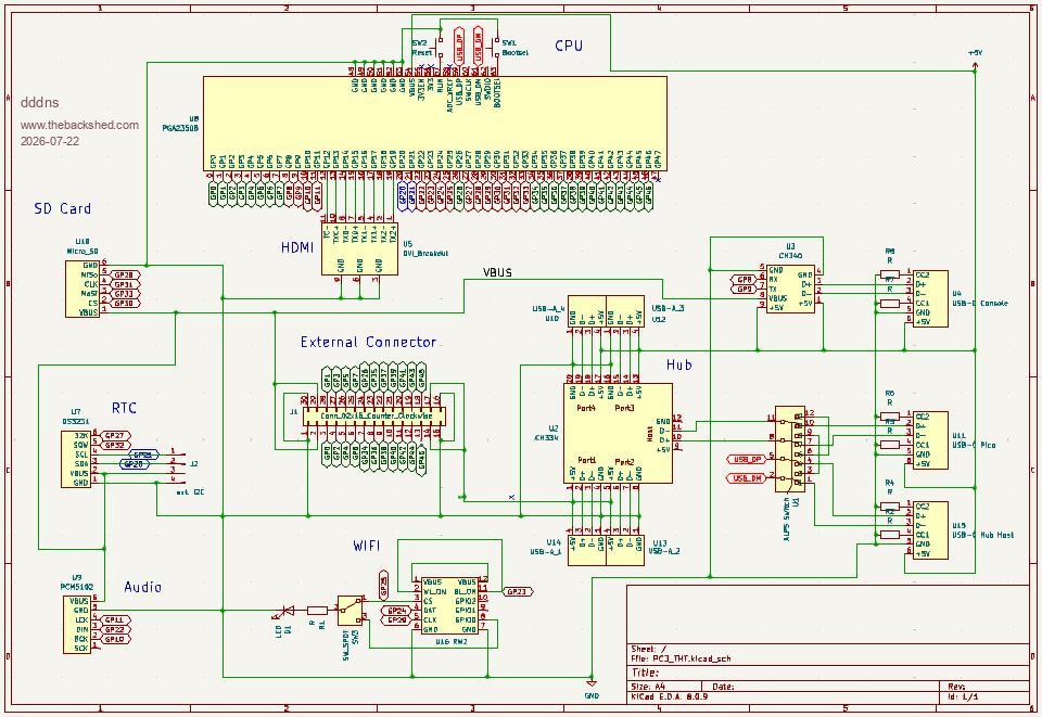
Hello! I created the footprints in KiCad 8 based on pictures because my paypal account is blocked. So they might need to be corrected in detail but it offers already something to experiment with to find the right placement of the parts. The schematic and routing are not done yet. The archive contains a subfolder symbols_footprints where you can find the libraries which need to be added to your KiCad install. I think it can be built on a single-sided 100x150mm board. Have fun :) 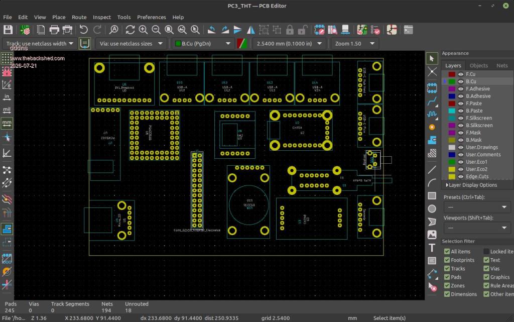 PC3_THT_KiCad8.zip I own some of these very nice ALPS switches so I used it.. Edit: The modules are all the above but the USB Serial converter is this with desoldered plug. Edited 2026-07-21 20:44 by dddns |
||||||
|
||||||
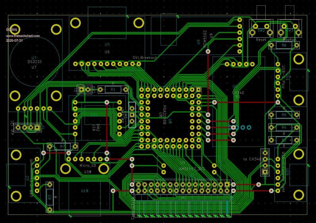
I wanted to make sure that it can be done single-sided so I did some routing. The red traces would be the front copper but these 15 vias are just copper wires (0 Ohm resistors) which can be soldered from the top. All modules are placed on one 2,54mm pitch grid so it will fit exactly like this on a perforated board. The SDcard could be turned 90 degrees then heading to the front. 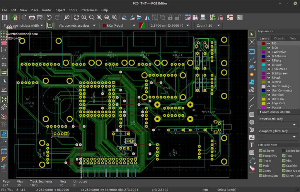 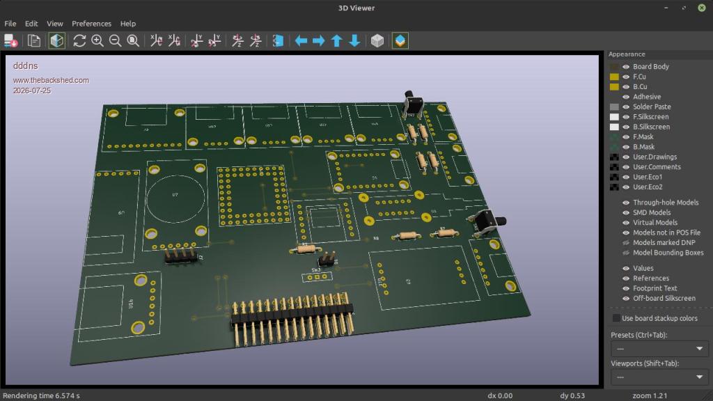 PC3_THT_2.zip |
||||||
Hello :) I ordered everything, and the parts are coming soon. Back in December 2024, I ordered two PGA modules from Pimoroni, which cost me less than 30 euros at the time, including customs and shipping. Today, customs alone costs almost 30 euros, and that was too expensive for me! The Adafruit 4-port hub isn't that easy to find either. So I'm building it with a PGA2350 A2 and without a hub: 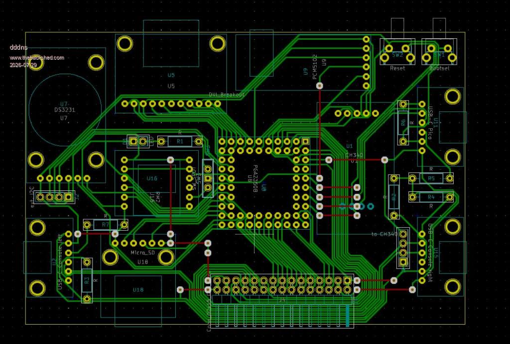 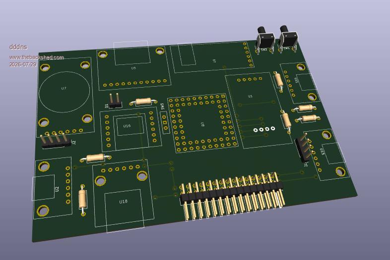 PC3_THT_basic.zip I'll check everything again tomorrow, but I think that's exactly how I'll set it up on the perforated board. As PCB it is a 120x80mm single-layer material and is ideal for etching with acid or milling..or ordering :)) Edited 2026-07-29 09:00 by dddns |
||||||
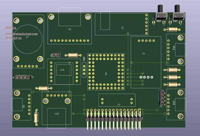
All parts arrived :) I added a dedicated AMS1117 for the VBUS supply because the Chinese SC662K on the USB UART adapter looks like it cannot handle more than 250mA current. First impression how it will look: 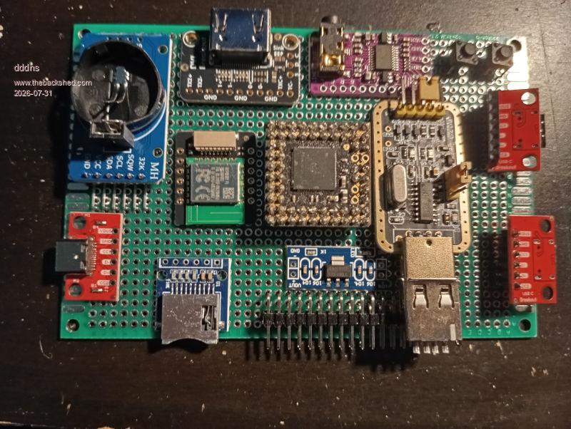 |
||||||
If you need maximum WiFi range perhaps that module could be put next to the HDMI socket with the antenna at (or beyond) the edge of the board. The RTC module would then need to be rotated 90° |
||||||
Hello Phil, I would like your suggested placement better as well. I looked at it for an hour but I can't find routes then and would need to add via's but there no place for them. The routes of Wifi GP23,24,25,29 cross RTC GP20,21,27,32 and to break out the inner pins of the PGA there is no more free gap either.. I will now need to rework the footprints and routing precisely and post the updated project files. Regards Edited 2026-07-31 17:02 by dddns |
||||||
Any copper at all under the wi-fi antenna will reduce the range. I don't think you have a lot of choice here, although if it is raised from the board on its connectors and you remove top and bottom copper areas immediately below the antenna it may work. It would be similar to a Pico W in free air then. I don't understand your comments about VBUS. It's a 5V supply, not 3V3, and doesn't need a regulator. Have they really restricted the VBUS output on that module rather than just using a fuse? The CP2102 module simply has a 500mA fuse (which I've never tested - I assume it self resets!}. . Edited 2026-07-31 18:14 by Mixtel90 |
||||||
Thanks for your comment Mick! I plan to solder all modules with pin headers and the board with sockets. So the RM2 will sit about 10mm above any copper. But I moved the traces underneath out of the way. All modules need 3V3. The PGA's regulator is too weak, the whole thing crashes if you only connect a SDcard to its 3V3 output. The regulator on the CH340 module is not better in terms of max current. The dedicated AMS module has the advantage to be a common solution for VBUS supply. Anyway, to adapt an USB UART module is a challenge if you would want to have a common solution that can be tinkered by everyone. That's why I'm providing the source files if one would like to modify it in some way. Sure your CP2102 could fit as well. Regards |
||||||
|
||||||
Actually there's not much that needs 3V3. The I2S module, HDMI, wi-fi and hub all use 5V. The RTC current is tiny and the SD card is intermittent (which is why it is filtered). Most of the 3V3 load (apart from the RP2350 chip) is the GPIO port. |
||||||
3V3 is RTC, WiFi, SDcard ,I2S and the unknown power used through the external connector! 5V is PGA2350 and USB UART. The GPIO's should be used as logical outputs but are anyway supplied by the PGA's regulator. Edited 2026-07-31 21:02 by dddns |
||||||
The I2S module I have has a linear regulator from 5V on board. It has a 3V3 pin after the regulator so it seems to be optional optional, handy for tying config pins high though. The RTC current draw is almost insignificant. Your schematic shows the wi-fi module powered from VBUS, not 3V3.... |
||||||
Nice Sunday! I printed some spacer and placed the parts like in KiCad. Problem is, that my perforated board has 2 rows too few in both directions. I compensated that for this prototype but will leave the design as it was but it is polished. All the mechanical parts are now done and I want to wire it with 30AWG wrap wire: 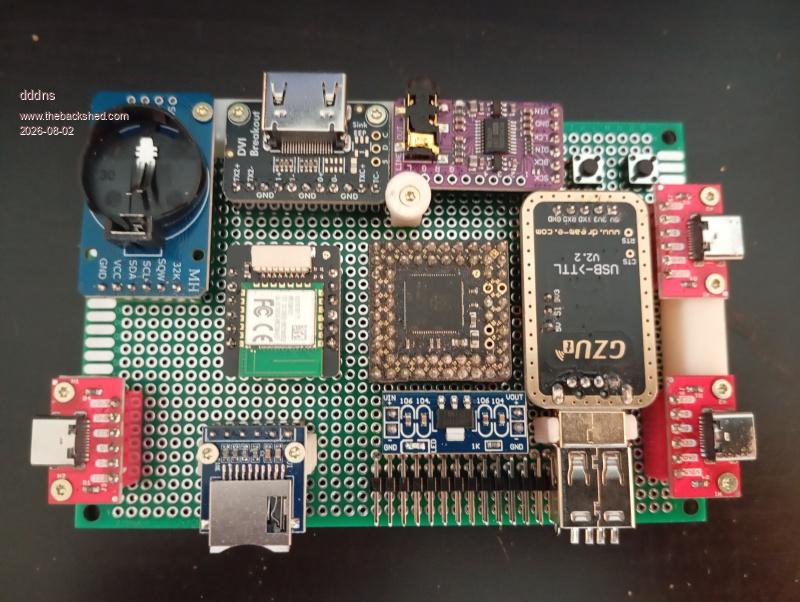 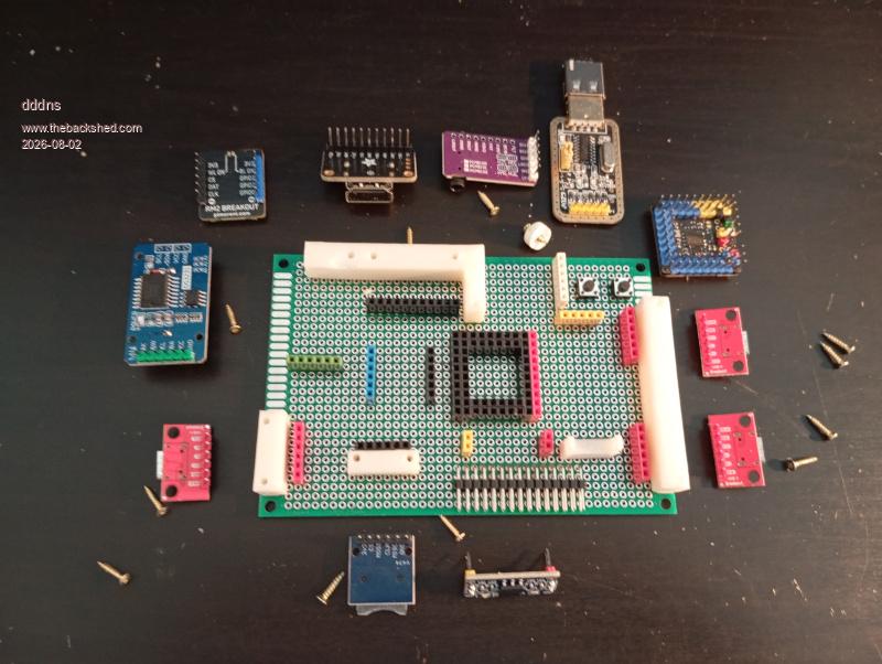 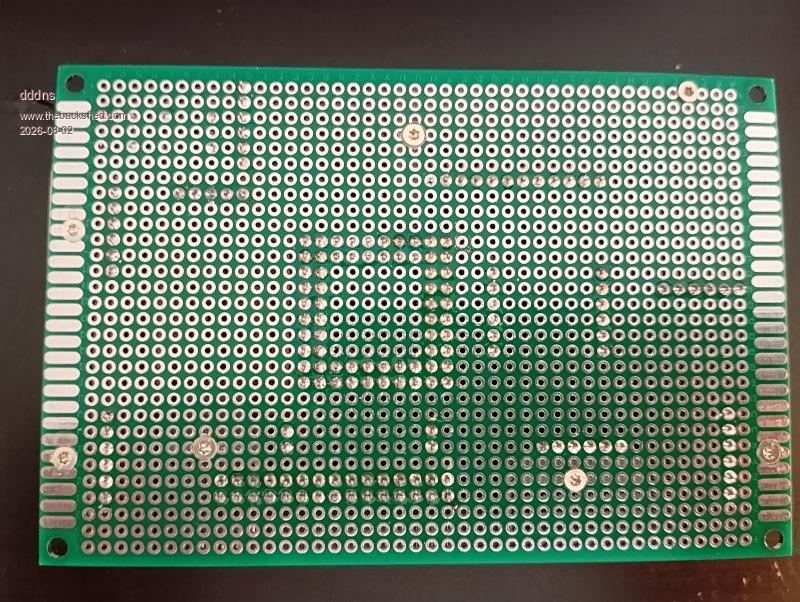 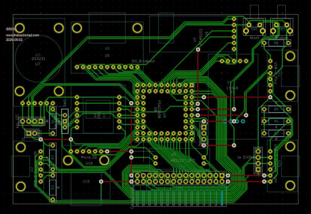 PC3_THT_mini.zip |
||||||
Why not swap the wifi module and the clock module. That way the wifi can overhang the board. |
||||||
Been doing this recently. Fun for prototyping  |
||||||
Thank you very much for your comment. Phil has already addressed the issue with Wi-Fi range. I always listen to feedback and have already tried this out. However, that would require at least a few additional via's, and I really want to keep the board single-sided. I’ll take another closer look at this! I’d like to print another enclosure and have the jacks flush with the surface. A protruding antenna wouldn’t look very good, so I have the following idea: We could use the jack that Pimoroni uses and simply attach the module mechanically to the cover, then connect it to the board via the cable before closing the enclosure. I think that could be a pretty elegant solution!? Update: The Wi-Fi module's antenna is now positioned at the very edge. The routing looks good this way, too. 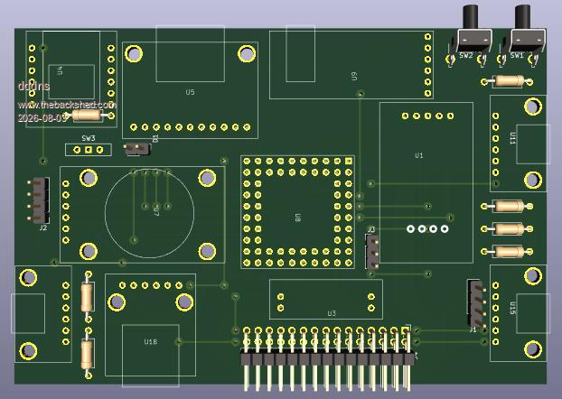 PC3_THT_miniV1.zip Edited 2026-08-03 17:35 by dddns |
||||||
| Page 1 of 6 |
||||||
 |
The Back Shed's forum code is written, and hosted, in Australia. |