
| Menu | JAQForum Ver 19.10.27 |
| Menu | JAQForum Ver 19.10.27 |
Forum Index : Microcontroller and PC projects : Gemini, Claude, and ChatGPT can design PCBs -- sort of
tldr: Claude and ChatGPT can run Kicad internally to themselves and iterate to produce netlists, eliminate DRC errors, place, and route, and generate gerbers. But with presently limited scope, and not helped by my limited ability to provide guidance This is a week-long journey now, and I had no idea where I'd end up. I started with a solar thought experiment with Gemini for Cuba (having run similar ones for Pakistan, African agricultural solarpunk, the Philippines, and Australia). What would it take to make Cuban residences largely independent of the failing grid? The Cuban situation is somewhat unique: grid is approximately 1950s U.S.era design--nominally 240V split phase with 2 120V legs, typically no more than 60A service. Many Cuban residences have only a single 120V leg and service as low as 30A. Since the beginning of July, the grid has had at least 4 systemic multi-day blackouts, and households are used to local blackouts of 18 hours a day or more. Gemini's conclusion: 2-6kW of panels (ground-mounted), 3-12kWh of batteries, and a 3.5-4kW single phase 120V inverter/charger could provide 9-20+kWh daily for potentially a little more than $1,000. The sticking point is the inverter/charger--it's a fairly unique design which needs to be very competitively priced. Gemini estimated a Chinese manufacturer would need an order of 10,000 or more to make a custom design. I asked Gemini if it could make the design. It cheerfully answered, "Yes". So it came up with a verbal spec. I asked it to make a Kicad netlist (I've used EasyCAD and EasyEDA, but not Kicad). It produced the .net file. I imported it into Kicad, got a bunch of errors, passed those back to Gemini, got a new .net file and repeated. It was going to be a slow process with me in the middle. About then I got a message from Anthropic giving me a $100 credit to use with Fable 5. My first thought was that I wouldn't know how to use it since Opus 4.8 has been entirely satisfactory for talking directly to the hardware (Pico Computer 3 or any PicoMite 2 W or Dockstar running OpenWrt) and producing the programs I ask it to--vibe coding to the max. My second thought was, maybe Fable can do this PCB design. So I set it to the task, with me still in the middle. After a few turn, it said something which made me ask it if it was able to run Kicad internally. It said probably, if I downloaded to the the Linux AppImage version which matched my own. I found kicad-10.0.5-x86_64.AppImage.tar, downloaded it, and Claude confirmed that it could iteratively work through import and then DRC errors until it could give me an error free .net file. I asked it to go further and produce a .kicad_pcb file from which I could produce gerbers to send to JLCPCB. Gemini suggested a placement layout, and Claude gave me the unrouted .kicad_pcb file which I double-clicked on and it brought up the PCB with ratlines. I could see that one component with long ratlines would be better placed elsewhere, so I suggested that placement to Claude and it came back with a much better-looking layout. I then asked it to do the routing. It talked to itself for a long time. Finally it had a file for me to double-click on. Everything looked routed, but the diagonal traces were stairsteps. I went back to Claude, and it fixed it 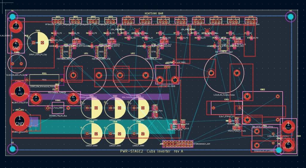 Pretty nice looking, I thought, but what do I know? So I fed the design to ChatGPT and it came back immediately and said, "Won't work. It's a buck design and you can't buck 48V DC to 120V AC--you need to boost it first." So I asked Chat if it could run Kicad internally with the AppImage. I gave it the tar file, and it said it tested out. I asked it to look at Solar Mike's Multi Phase PV Charger. Mike didn't include design files, but has many images of schematics and PCBs. I saved the browser page, which include a folder of images, and uploaded it to Gemini (which is perhaps the best AI with images). It figured out a .net file and recommended some parts changes--200V IXTP120N20X4 mosfet, FAN7382 gate drivers, unidirectional ACS770ECB-200B current sensor, MUR120 diodes. Gemini said it can't run the Kicad AppImage, so I asked it to produce a handoff document for Claude. So Claude started work on it and finally produced a .kicad_pcb file, which it said was strictly a prototype for bench testing, and needed to have copper bus bars bolted on as Mike's design did. I produced gerbers and sent them to JLCPCB--$15USD for 5 boards. But again, what do I know? I'll have to use entirely new-to-me protocols in testing this relatively hig-voltage design (I've not previously worked with more than 24V). And the inductor is off-board. Anyway, at this point, I had $.31 remaining of the $100 credit for using Fable, so I asked it to produce a How-To document. I switched back to Opus 4.8 and asked Claude to produce the Pico 2 W controller board for this MPPT PCB--communicating through the 2x10 header. That was yesterday evening. After several "What up?" prompts after long periods with no output, it says it's still working on routing. Apparently it has to figure out a different toolchain from what Fable was using. Claude did eventually route a controller board based on the Pico 2 W with an ADS1115 ADC module. It's not a very complicated board, and it worked on it for hours, routing and rerouting, with occasional prompts from me to wake it up. 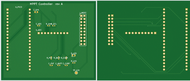 Apparently there are a lot of command-line helper programs which people have developed to work with Kicad, and Claude and ChatGPT are experimenting with them. For instance, there's a routing tool, FreeRouting, (which seems so far not to be working entirely). So that's progress to this point. At the very least, getting a clean .net file is a very big timesaver. Whether or not this whole end-to-end vibe PCB design works well right now, I suspect it will in 6 months. I've learned a fair amount about Kicad (though I haven't actually placed a part or drawn a trace yet). Thanks to Solar Mike for his designs. I've been watching since he was using PICAXE MCUs. And to other shedders in the "Electronics" forum PicoMite, Armmite F4, SensorKits, MMBasic Hardware, Games, etc. on FOTS |
||||||
Cool, interested to see how you get on. I do all my designs in DipTrace, it can export out in various other formats, although have never used that functionality, happy to do that for you, send me a PM and I can see what I can or cannot do. Cheers Mike |
||||||
I haven't tried using them to design, but I have used Claude to do a design review. I passed it the gerbers, schematic and easyeda design file. It took some time but found a complex issue on the design, made other less important suggestions and validated the basic design overall. It went out for the chip datasheets and all other documentation it needed itself - pretty impressive stuff |
||||||
I keep seeing ads for Flux.ai |
||||||
Prompt to Claude: "Please provide a link to and summarize OpenAI's recent introduction of the Astra GPT-6 model with respect to its ability to design PCBs using Kicad." Response: |
||||||
I couldn't have put it better myself. Get the placement right and you are a long way there. Return current paths can be a pig. |
||||||
 |
The Back Shed's forum code is written, and hosted, in Australia. |


