After battery Box upgrades, and making new copper plate BUS bars for the new layout, I finally rewired and refitted some existing 0 gauge and new 00 gauge wiring, it was easy to redo everything while still staying 100% off grid. The black-box mid screen and to the right, is a Touch screen BMS setting Controller and Monitor, it selects any of the battery BMS units, and also selects any of the Battery balance modules in the battery units, and allows setup and adjustment to them as well. As the shed is lined and insulated, it does not get below 14°C overnight in winter and is air conditioned in summer, remaining below 29°C, air-Con sometimes runs all night, as does one or two of the units in the house. FULL electric home and big machinery in the workshop, SOC is never below 50% except with extended periods of black overcast weather. Mains has been off for over two years now, the only thing connected to mains is 16 year old solar in-feed unit, that is until the rebates finish or it claps out, I think rebates will finish first, then a new solar array of panels will replace the old in-feed array and connect into the existing off-grid setup via another solar regulator or two. You can guess what will happen when that is finished shh! For now, no E-bills, always in credit, even after transferring most of the ever increasing credit out every 3 quarters or so. I know I sound like a broken record, and here is a another broken track, the WG Inverter is a Beast. 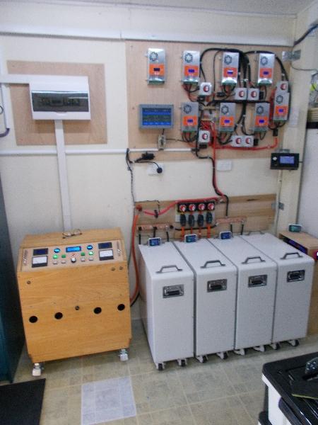 |


 , you will have to find something else to do after this.
 ...I'm sure you have plenty of interesting stuff to do.
