Posted: 03:28am 08 Nov 2025 Copy link to clipboard
oreo Senior Member
Well, from January to November the hydro rates have gone up about 6% here. There was no price increase in the cost per KWH, however the electricity rebate was reduced from 19.3% to 13.1%. No big deal. However the new rates that just started in November are considerably more expensive. The rate plan I am currently on has increases ranging from 28.7% to 39.3% (different increases for different usage times). I suspect that they will initially employ a much higher rebate to reduce the number of complaints and then just reduce the rebate over time.
Of course this just gives me more reason to stop being so lazy and finish building up the second transformer so I can move more stuff over to the inverter. The items I would like to move over are A/C, stove and dryer. I have all the materials for the inverter, but will need some items to beef up the battery charger.
Note: After a little googling, I see that the rebate has gone from 13.1% to 23.5%, which makes the effective increase from 16% to 22%.
I guess the party is over.
Edited 2025-11-08 13:44 by oreo
Posted: 03:59am 08 Nov 2025 Copy link to clipboard
KeepIS Guru
Love the photo, we will be facing a similar problem here before long.
I can report that I'm still 100% off grid with total disregard to the power we are using, dual ovens, Hotplates, washer dryer, big hot water system, 3 aircons, workshop, and on it goes, through winter and a few days with low solar and two days with almost none, lowest battery level was 38% after two days of no solar.
I'm still amazed, the Inverter has seen 14kW at times, and often runs with constant cycling between 8kW to 10kW for an hour or so each day. It runs virtually cold, highest FET heatsink temps were 38° and the Toriods have never gone above 42°, which basically feels like a slight warmth to the touch on a 37°c day . Edited 2025-11-08 14:00 by KeepIS
Posted: 07:09pm 04 Jan 2026 Copy link to clipboard
oreo Senior Member
I hope everyone had a wonderful Christmas and are set for an eventful 2026!
I did a bit of work in December on the system, mainly because I got my hands on a few more batteries on the really cheap. I was not planning on expanding the battery, but you know how these things go.
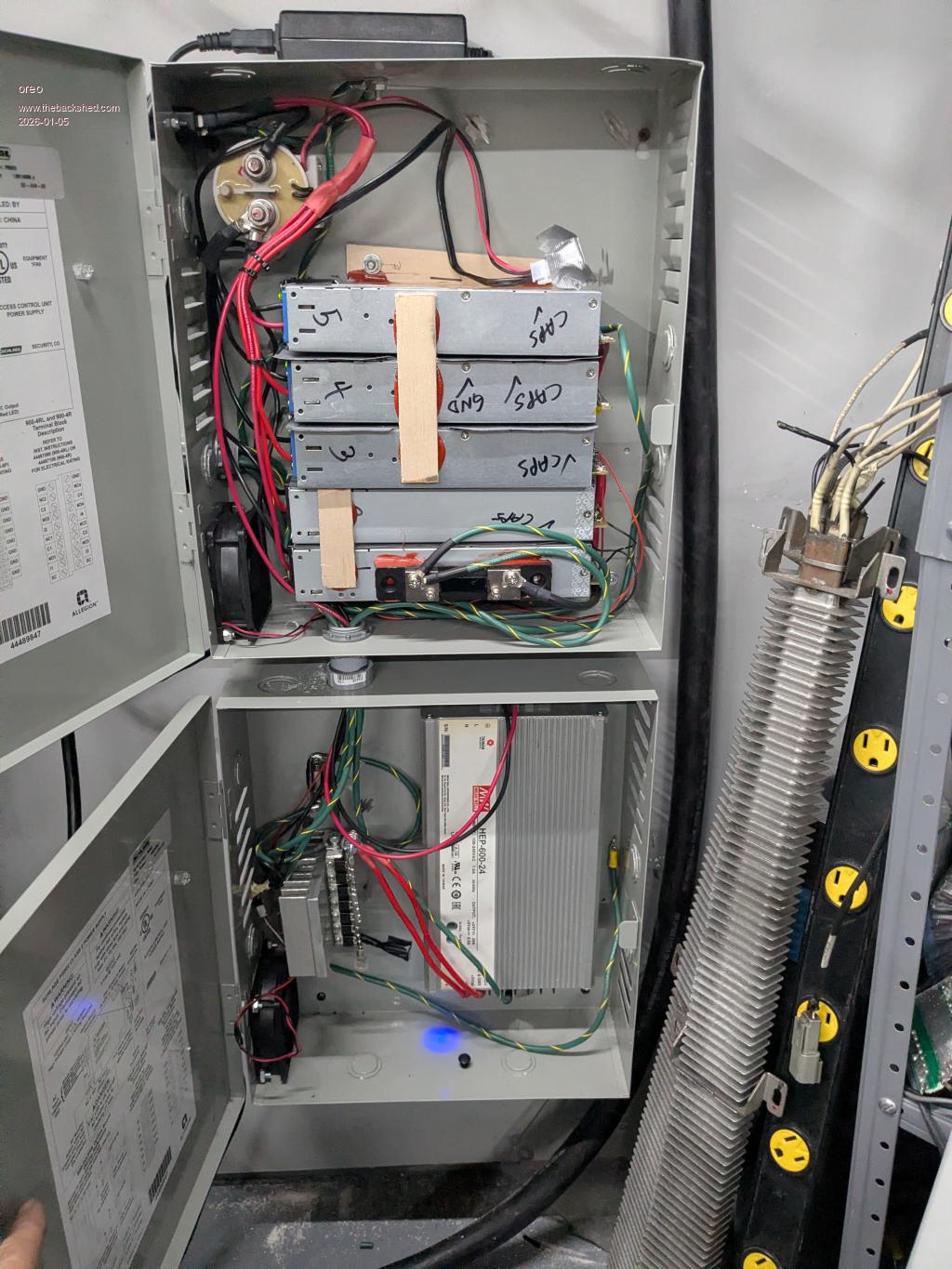
So right now I have 2 batteries, one with 26 internal 36v packs and one with 20 internal 36v packs. On top of the smaller battery, I have the MPPT and battery charger mounted. So the plan was to relocate these 2 items, so I could add another 6 packs to the 20pack battery.
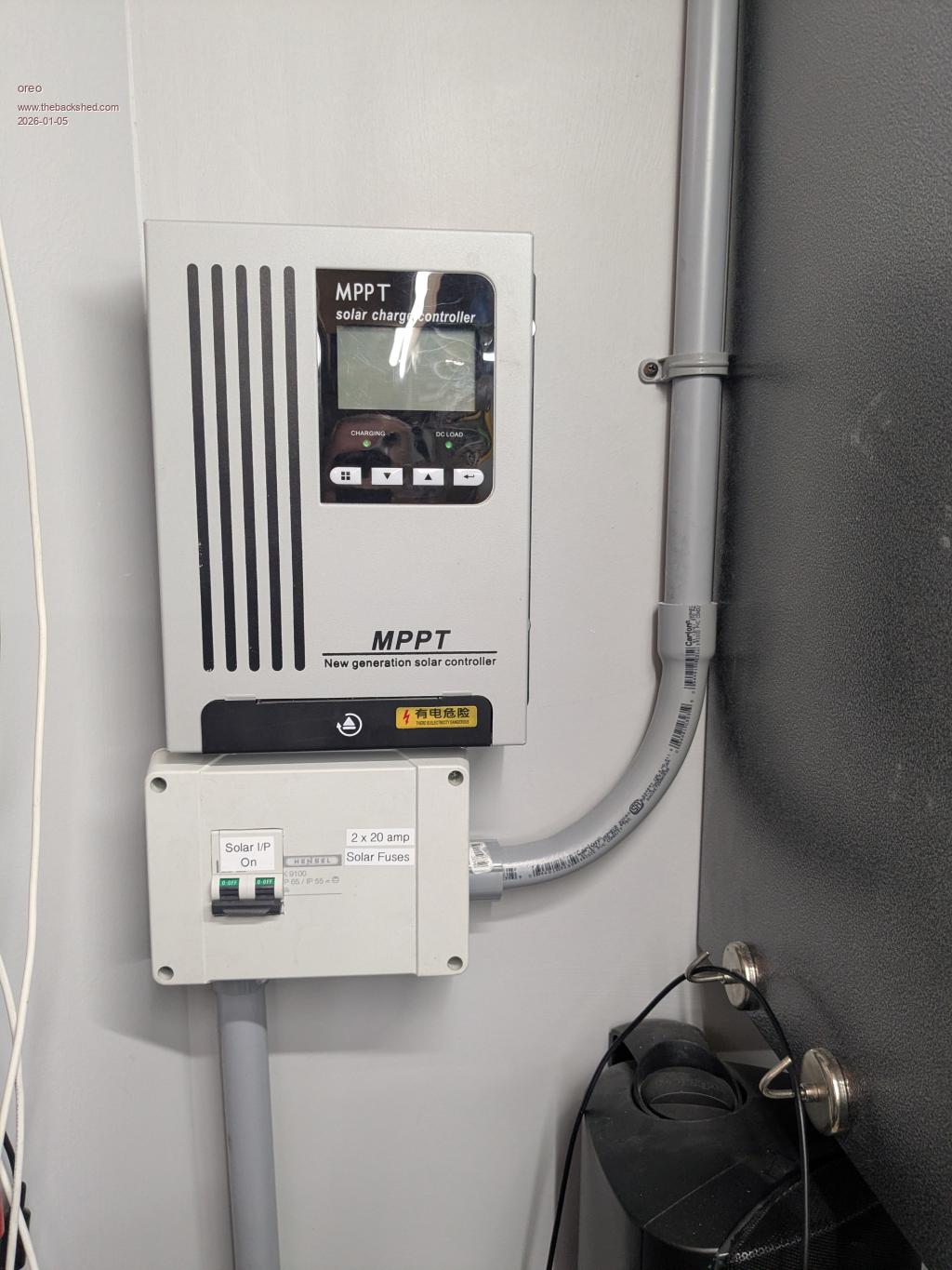
Moving the MPPT was fairly easy, as I just moved it to the wall.
Rather than just move the charger, I decided to upgrade it. Theoretically, my previous charger should have been able to charge at 25amps (~1950w), however it used 2 12.5amp 54v power supplies in parallel, and each supply tended to hog all the current, and then shut down. I jury rigged it by putting some resistance in series with each power supply, but every once and a while they did not play nicely. This led me to reduce the current to about 20amps. On top of that, the efficiency of the setup was not ideal, due to this resistance and also the fact that I had a diode array in series with the supply to stop back flow of current. This array had a drop of about .68v across it.
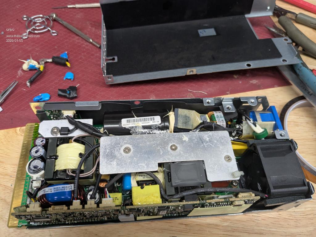
So I ended up replacing the 2 12.5a 54v power supplies with 5 12v power supplies. (2 are SUPERMICRO PWS-1K02A-1R and 3 are HP HSTNS-PL29) I also purchased another Mean Well HEP series 24v supply, with adjustable current limit, however this was a 13.3 amp unit to put in parallel with the 25amp unit I have. In all, this should theoretically yield close to 3kw of charging power. I replaced the series diode bank with more V40100C diode pairs to drop the forward voltage to .40v.
One of the problems with using these cheap 12v power supplies, is that as supplied each connects the -ve rail to the ground pin on the AC and they have many capacitors between the -ve terminal, and the live AC for noise suppression. When you string a bunch of these power supplies in series, even with their AC ground pins unconnected, there is quite alot of AC being injected into the dc by all those capacitors in the group of supples. So I opened up the supplies and removed the capacitors.
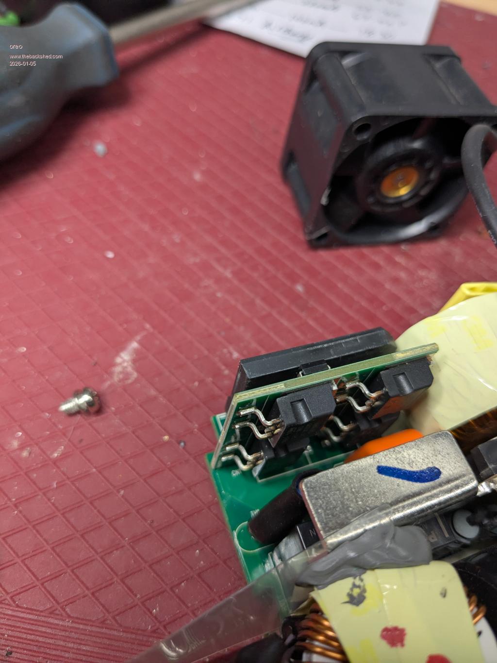
Some of these supplies are 96% efficient, and I see they are using FET's to reduce the forward drop on the AC side bridge rectifier. Very cool.
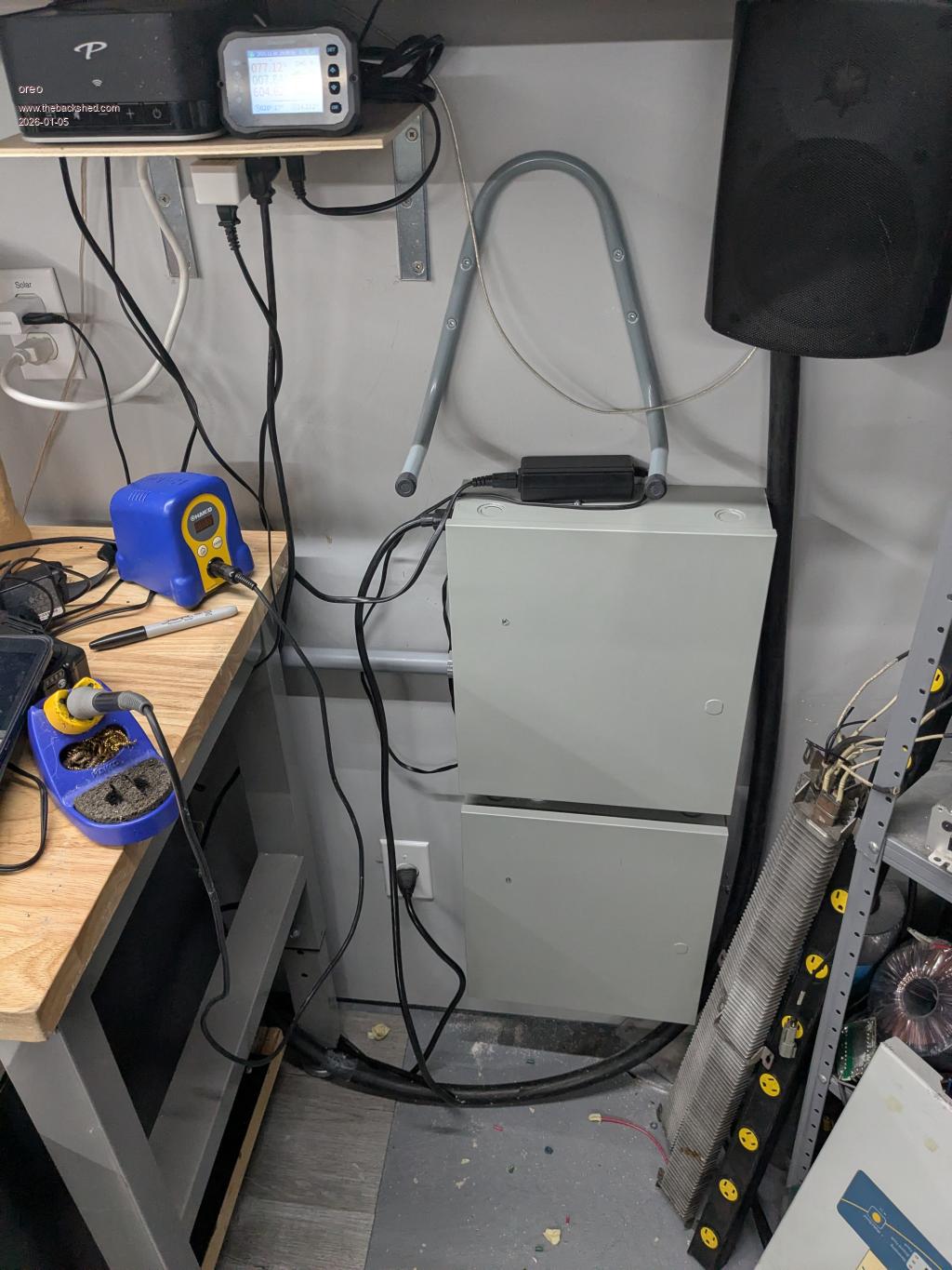
Anyway, I mounted these supplies in some boxes I got off marketplace, and mounted them on the wall. I still have work to do here, as the 13.3amp supply has not arrived, and I want to add more functionality to the charger.
Posted: 07:59pm 04 Jan 2026 Copy link to clipboard
oreo Senior Member
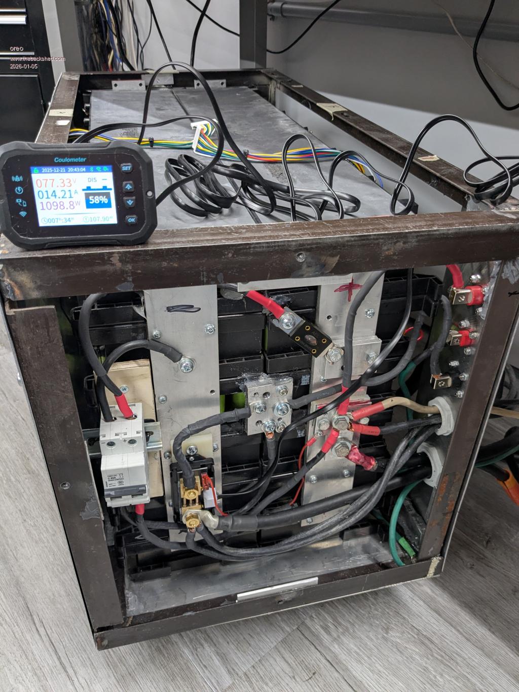
So now the top of the battery was clear, however I had added items onto the battery in a hodge podge manner and had wires entering the battery on 3 sides. So I took to opportunity to improve this by both increasing wire sizes and moving all entry into the box to the rear of the battery on a separate panel.
I also changed out the couloumeter to a Junctek KM110F which has wireless, so I can view the battery condition anywhere.
This is what it looks like now.
Everything seemed to be working well, and I was getting ready to install 6 more battery packs on the top of my battery, when the inverter popped.
I was in the basement at the time, and there was no change in noise level or anything, just the breakers on the batteries and inverter tripped. It was in the middle of the day, so there would not have been much of a load on the inverter.
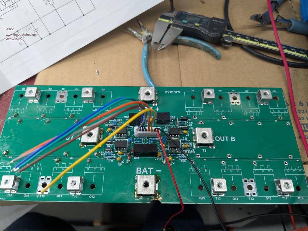
In testing I can only find that Q5-Q8 and Q13-Q16 have failed. The little power supplies and driver transistors are ok. I am thinking of using my back up board as replacement rather than fixing this one.. I can't see any other issues at this point. Thoughts on what else to check?
thanks
Posted: 10:19pm 04 Jan 2026 Copy link to clipboard
KeepIS Guru
Replace the gate resistors, they can be compromised, I had that issue after the old changeover ATS I was using arched Mains AC to Inverter AC and took out a few FETs.
I hope you can find the cause as this really should not happen with this inverter unless something like a flaky component failure or other external device fault.
Posted: 01:13am 05 Jan 2026 Copy link to clipboard
wiseguy Guru
I have re-read the last few pages of your thread and now I have a question, what choke cores are you using now? The page link you posted for amorphous nanocrystalline cores, I did not follow the link at the time as I assumed that you had found suitable similar cores. After taking a closer look, the ferrite in my opinion is totally unsuitable for this type of inverter. It is usually used for transformers and EMI filters which require no energy storage, just energy transfer.
Maybe I read it wrong but it sounded like you gapped some of these cores so they would have lower inductance and have some energy storage characteristic. I strongly advise you reconsider those cores and go for the powdered iron type cores instead. I would use steel c cores gapped due to their softer saturation behaviour before I would use gapped ferrite .
Sorry to hear of the failure - maybe you no longer use the ferrite amorphous nanocrystalline cores in which case I will have a rethink as to what else may have caused the failure ?
Great pictures and good to see the setup you have put together. Edited 2026-01-05 11:13 by wiseguy
Posted: 03:01am 05 Jan 2026 Copy link to clipboard
oreo Senior Member
Thanks for the comments!
I did measure them, but you're right they're easily replaced.
I never actually used the gapped amorphous nanocrystalline cores on the inverter. I have always used 2 sets of 5 stacked MS-184040-2 cores (sendust) with 9 turns, each resulting in 38uH at 5 amps, 25uH at 80 amps, dropping to 15uH at 160 amps.
I need to look further to see if I can find any other issues...
Posted: 07:11pm 05 Jan 2026 Copy link to clipboard
analog8484 Senior Member
Since you are not using the typical 48V battery bank with the HY4008/HY5608 setup ...
Did you ever check the gate drive waveforms? Just to rule out potential anomalies that could have degraded the MOSFETs over time.
Posted: 03:32pm 07 Jan 2026 Copy link to clipboard
oreo Senior Member
Thanks for the suggestion. I believe I did check the waveforms when I first got things running, because the power draw was a little more than I was expecting. Of course this is a while ago, so I don't remember details exactly.
At this point, I have a few parts on order from Digikey, so I can complete the build on 2 complete sets of boards. This way I will have 2 complete running sets of boards to play with/compare.
Once I have these boards running, I should have some time to review everything.
Posted: 03:57am 20 Feb 2026 Copy link to clipboard
oreo Senior Member
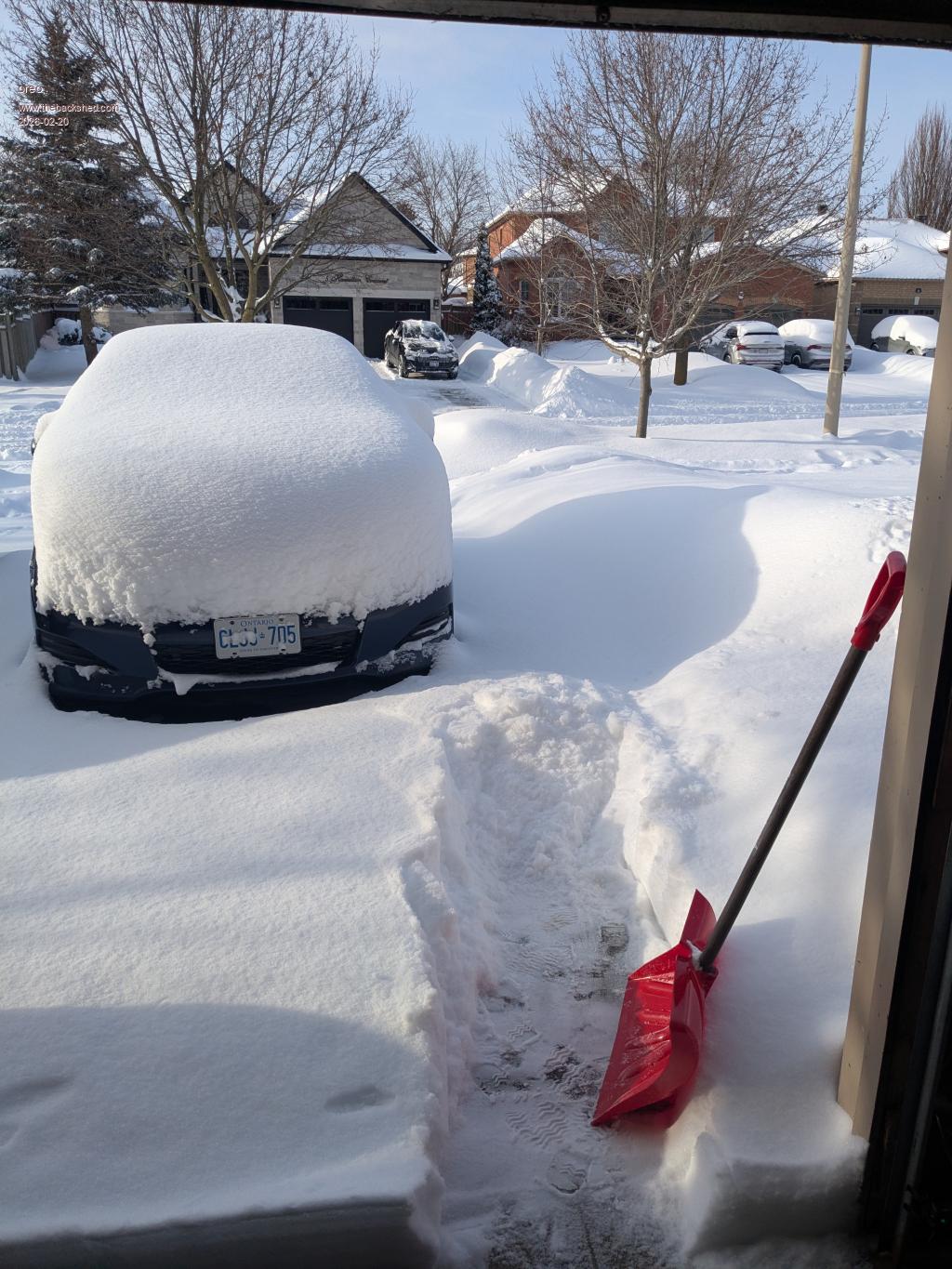
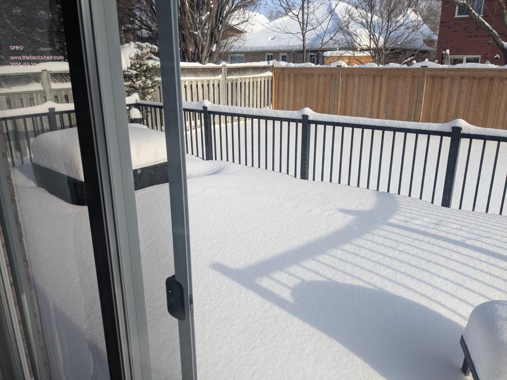
Update I was watching the Australian open a few weeks ago, and saw highs at the courts of slightly over 45C. That is warm! Meanwhile, we had 29 consecutive days of below zero weather, due to a shifted polar vortex. This is a record for this area. This also lead to higher than normal snow accumulation. So not bad compared to lots of other areas, but more than we expect.
Regarding the inverter, I have done a few things. -the 8 Fets (Q5-Q8 and Q13-Q16) were blown, so I replaced those and the the inverter ran. -I then also replaced the driver transistors, gate resistors and thermal pads just because. -I had a spare power FET and aurduino board mostly built, so I completed those and made another aluminum mounting plate for the power FET board. These new boards were installed into the inverter, and the old ones kept as backup.
I had a piece of audio gear that drew a huge inrush current (120A at 120v). I modified it so most it draws now is about 10 amps. This allowed me to greatly reduce the over current trip point of the inverter.
Things have been running fine for the last few weeks, although the frequency on this new arduino is not particularly good.
So all is good...
Posted: 02:08am 08 Aug 2026 Copy link to clipboard
oreo Senior Member
A tale of 2 mosfets
So, as mentioned earier, I have had an issue popping FETs. Over time, I determined that the problem occurred when the load presented to the inverter, went over 7.5kw. This includes any surge. 7.5kw seems like a lot, but items like my AC unit draws 12kw on startup.
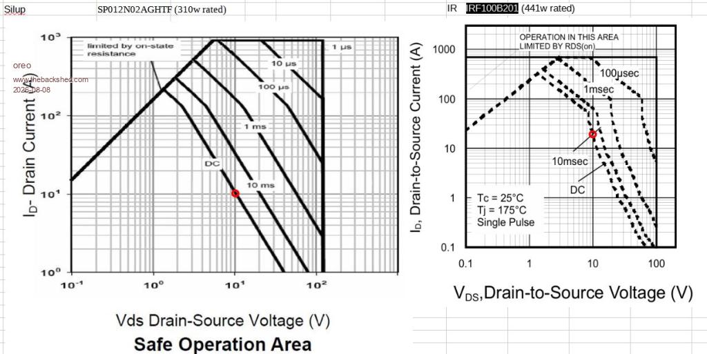
It was time to order some replacements, and up to this point I had been using the Siliup SP012N02AGHTFA. I was using this part, mainly because the Huayi HY5012W had been on backorder, and the Voltage/Max Current/RDS(on) on the Siliup part was similar. I reviewed the data sheets again, and noticed that the SOA curves for the Siliup part looked weird. Although the part was rated at 310W, the DC curve showed the device could only withstand 10A at 10V Drain-Source which is 100w, not 310. Looking on the manufacturers website, the SP012N02AGHTFA has been replaced by the SP012N02AAGHTFA and the SOA curves look normal for this new device (at DC, the current x Voltage = device power rating. Anyway, after a bunch more searching, I found another device that had SOA curves like the Siliup part, the IR IRF100B201. At dc and 10v, the graph indicates the part will withstand 20amps or 200w total, while the device is rated at 440w.
Maybe I am missing something, but I ordered the HY5012W's. (note that the HY5608W will not work for me, as my battery voltage is 72V nominal)
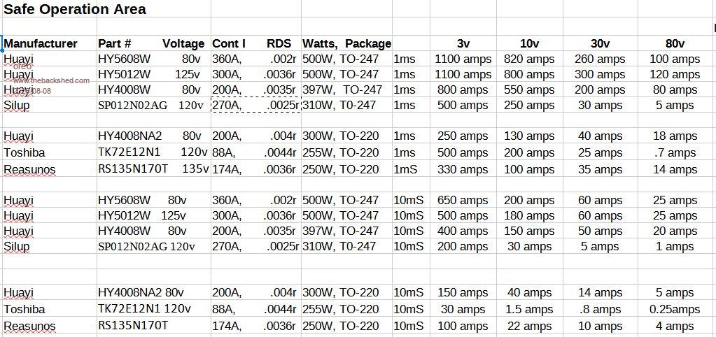
While waiting for the parts, I looked at a huge number of SOA curves, and couldn't really find any devices that matched the Huayi parts. Here is a chart showing a comparison of some of the numbers derived from the published curves for each device.
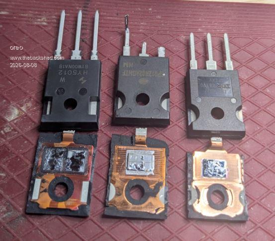
After the parts arrived, I popped the top off one of them to compare.
Yes, the HY5012W actually has 2 FET dies in there. There are wires encapsulated in the plastic that connect each die to the outer pins.
Here is a comparison of surface area of the dies.
Looking at the specifications of other Huayi FETs, it looks like the 2 dies are from the HY3712B. That is one way to get a superior FET without designing a new part!
So now I understand why the wiseguy inverter was underperforming with the Siliup Fets. I still need to do some further testing, but for now I have raised the current limit. Edited 2026-08-08 12:15 by oreo
Posted: 08:05am 08 Aug 2026 Copy link to clipboard
Solar Mike Guru
Those points marked in red on the SOA curve are the steady state DC level, your mosfets are not permanently at that point on the SOA curve, they are or should be turned on in a few tens of nano-seconds, thusly the current capability increases as shown higher up the curves with decreasing on times.
Most likely it is a voltage spike thats killing them, 72v battery voltage, you need really 150v mosfets, perhaps the circuit requires the correct snubber RC network across the Drain\Source pins to control any voltage spike or ringing; look at it on a scope; generally the more current drawn the larger any ringing spikes.
Moving to compound die mosfets doubles the charge currents needed to switch them on in the shortest time, having 4 paralleled places a lot of extra stress on the mosfet driver and its bias supply, if the bias supply sags and cannot supply the required driver current then that will also blow them up, if you go for dual die versions, then a 2watt psu for the bias would be needed.
Cheers Mike
Posted: 04:23pm 08 Aug 2026 Copy link to clipboard
analog8484 Senior Member
Interesting to see the double dies in the HY5012W. Given that the blowups happen around 7.5kW, I think Solar Mike is right that it's more likely the FET's failed due to overvoltage than overcurrent. I still wonder if potential anomalies (e.g. Miller shoot-throughs) that degrade the FET's over time could be the failure cause.
Posted: 05:51pm 08 Aug 2026 Copy link to clipboard
oreo Senior Member
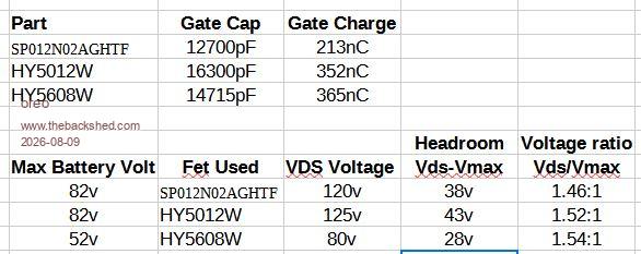
Thanks for the input Mike! Can you tell me how you arrived at me needing 150v Mosfets? I just linearly scaled up the 80v mosfets everyone else uses in the Wiseguy 48v inverter. (see calculations below)
While the gate capacitance of the HY5012 is higher than the HY5608, it does not seem to be that much different. (to me) I show the numbers below. I have checked the bias voltages in the past and will double check them again with the new FETs in there.
Edited 2026-08-09 03:54 by oreo
Posted: 12:38am 09 Aug 2026 Copy link to clipboard
Solar Mike Guru
From building numerous 1/2 bridge power circuits, some can generate quite high very short duration spikes, only picked up after looking on a scope trace, 72v base + a 40v spike is cutting it pretty fine using lower voltage mosfets. If you fire the thing up first at a lower voltage and spikes are low, then it would be safe to use a 120v device, or after measuring the ringing frequency and working out correct snubber values. I always go for at least 30% margin in device selection, thus my estimate of 150v; the common ranges are 80, 100, 150v noting that some Chinese manufactures also have 120v devices. I did use some Chinese manufactured 120v rated mosfets in one PV controller and they kept blowing up, even after measuring within spec Drain\Source voltages, Swapping out for 150v devices, never had a problem, does make me wonder at times about the validity of some manufactures published spec's.
Mike
Posted: 01:29am 04 Sep 2026 Copy link to clipboard
oreo Senior Member
So I compared the power draw of the power board when idling using the Siliup devices compared to the Huayi devices, and only found about a .1w difference. The bias voltages looked to be good, and then I realized that I was using 2w power supplies, so I have plenty of power supply wattage there.
Then I measured the avalanch voltage for both the Siliup and Huayi devices. The Siliup devices (rated at 120v) surprisingly avalanched at between 139 to 149v. The Huayi devices avalanched quite repeatably at 128-129v (rated at 125v). So all things equal, it would seem that if the issue is voltage alone, the Huayi devices are going to fail sooner than the Siliup devices.
I tried measuring the peak voltages while the inverter was running with different loads. I did measure higher voltages when driving larger loads, however I didn't have a short ground lead so was measuring much higher voltages than the devices were actually seeing. In the end, I decided to just push the inverter and see if it failed.
So far I have pushed the inverter to short term loads of 11Kw with no issues, so I am happy. Long term I plan on winding a second transformer and using a second power stage to drive it.
Power testing on the transfomer shows a temperature rise of 36C at 5100va to the load (sensor measures a 22C rise). Not sure how hot the inner windings might be getting. I think on the next transformer, I will bury a temperature sensor.
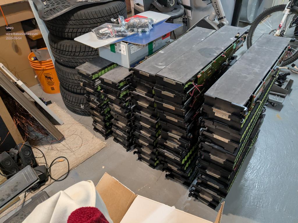
So I had decided a while ago that it was not cost effective to add capacity to my current battery bank (currently about 14kw using 24pcs of 36v packs using A123 26650 cells). Batteries are expensive and 14kw gives me about 1 days storage. Then I saw this marketplace advert. So yah, I had to pick up some.
I spoke to the people giving away the batteries, and they said that they had over 1000pcs in stock and they were not selling. Apparently they are expecting to get some all electric busses in for tear down and will soon have better batteries to sell (these batteries are out of hybrid busses)