Hi everyone,
I'm working on a custom Arduino-based inverter project that generates a 20 kHz carrier / 60 Hz fundamental complementary unipolar SPWM—same output style as the EG8010. I'm experiencing severe DC-side noise that’s affecting:
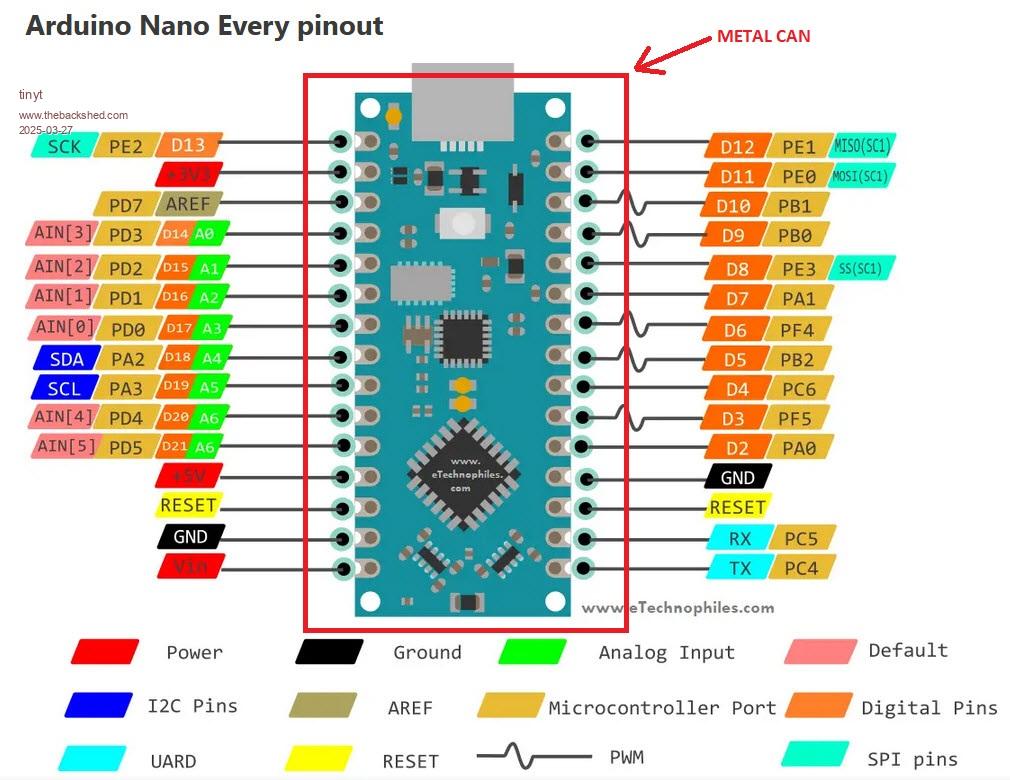
Arduino Nano Every (ATmega4809) analog readings
Serial communication (UART glitches and resets)
AC input feedback from sensors like ZMPT101B and WCS1700
System Details:
Inverter runs off a 36V–50V DC supply
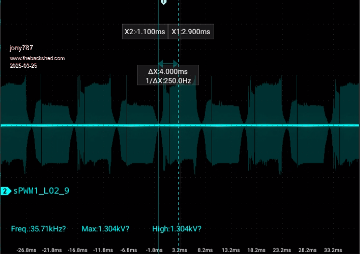
SPWM generated by Arduino Nano Every (60 Hz fundamental + 20 kHz complementary carrier)
DC rail has 4 × 10,000 µF bulk caps (PowerJack power board)
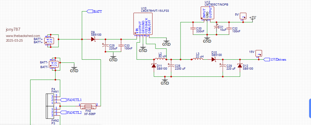
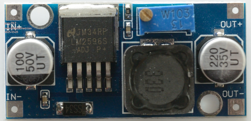
5V line originally from LM7805, now from LM2596 buck converter
Arduino controls H-bridge and senses AC output via voltage/current sensors
Images:
What I’ve Tried:
LC filter (82 µH + 2200 µF) after 5V regulator
100nF and 10µF ceramic caps at load
Common ground for all circuits
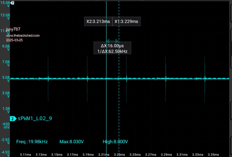
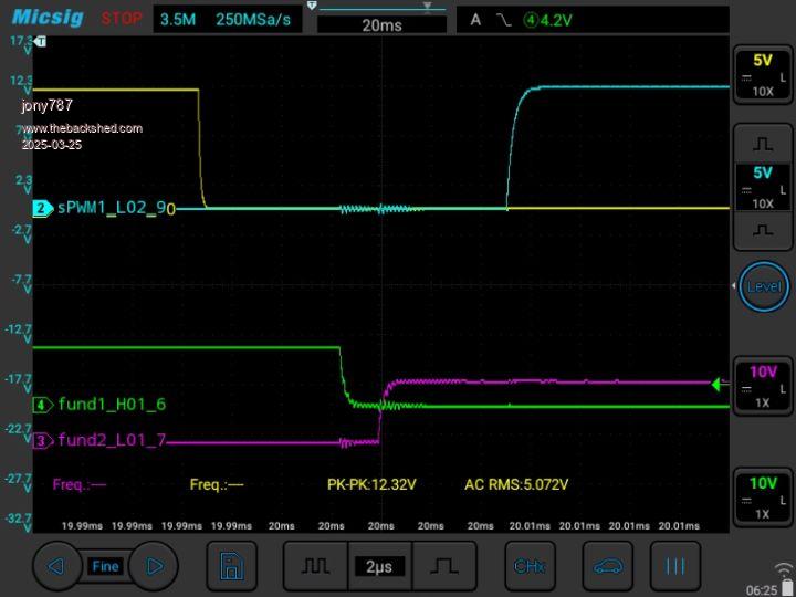
Scoped noise is ~20 kHz ripple/spikes riding both VCC and GND
Considering isolated DC-DC converter to isolate Arduino and sensors
Questions:
How are others managing DC-side noise in inverter or high-frequency switching systems?
Are you using fully isolated supplies?
Any success with ferrite beads, star grounding, or optical isolation for UART?
Are you isolating sensor power and ground separately?
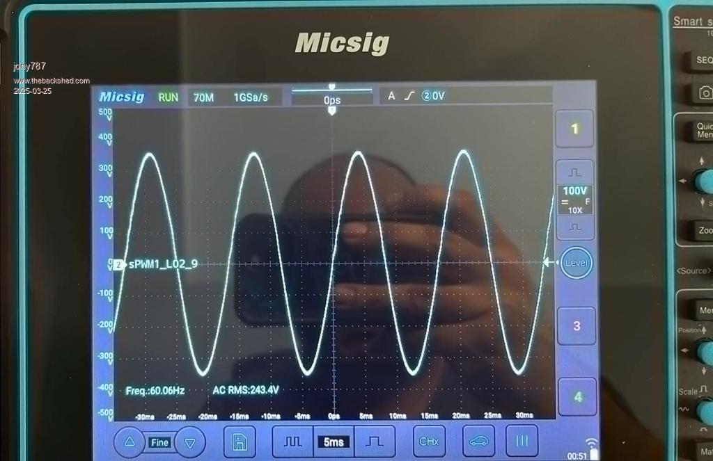
The sinewave looks good overall with minimal wobble at zero-volt crossover.
Thanks to Warpspeed for guidance on transformer tuning—I tuned the secondary close to 90 Hz with a 2.5 µF capacitor.
Right now, I'm powering the inverter from a DC bench supply during testing. The sine amplitude scales with DC input. The inverter is functionally working, but I must fix the noise to get reliable AC voltage/current readings.
Any feedback, schematics, or scope images showing how you solved similar issues would be hugely appreciated.
Thanks in advance.