Menu
JAQForum Ver 19.10.27

Forum Index : Electronics : Mosfet selection

Posted: 06:44am
29 Oct 2025
Copy link to clipboard
Dinosaur
Guru


Hi All

I need some advise on the parameters of selection.
Currently I have a number IRLZ44n N channel mosfets that I have been testing for my purpose.
Basically I need to switch 5V at a max of 10A using pwm frequency of 100 hz.

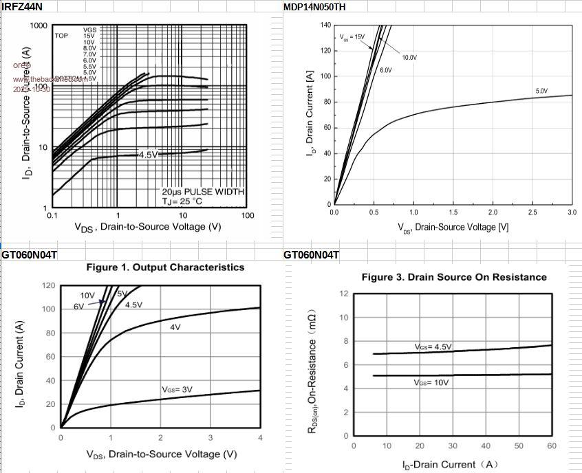
When you look at the spec of the IRLZ44N it has Drain current of 33A to 47A.
However when testing it with 5vdc  and slowly ramping it up to 5A, it got uncomfortably hot.
Although it appears that they are intended to run hot, however,
I was hoping to use an over rated unit that would not need heat sinks.

Again looking at the spec, RDs(on) goes from 22 milli ohm to 35.
I am using 1k in series on the Gate with 10k to ground.
Others that I am looking at have a Rds(on) of 3.3 milli ohm.

Other factors that probably contribute to the heating is that I am driving it at 3.3v
direct from the Rpi and it is probably not switched fully On.
So I have ordered a couple of 4 channel level shifters.
Basically a tiny board with mosfets to shift the logic level from 3.3 to 5v.
I will also lower the series gate resistor to 330 ohm, although with the level shifter
and the high impedance of the Gate, I may not need any series resistance.

I understand that the harder you switch it ON and the faster the rise time of the gate
the less heat it creates. The gate charge spec also seems to contribute to the heating,
but it goes down as the spec of the Rds(on) goes down.

So, my question is:
How far should I go in over rating current and voltage to satisfy that need.
The fact that I may pay a dollar or two more really doesn't make any difference,
I just buy ten of them and test them.

Regards
Regards
Hervey Bay Qld.
 
Posted: 07:31am
29 Oct 2025
Copy link to clipboard
phil99
Guru


Datasheet Fig. 3 - Typical Transfer Characteristics indicates you need 5V with a 10A load.
At 100Hz switching losses are a minor issue.

If you have any small general purpose NPN transistors one of them will do.
Connect the base to 3.3V via a 3.3kΩ resistor and the emitter to the digital-out pin. The collector connects to the gate and a 1kΩ to 5V.

When the DOUT takes the emitter low base current will flow and the collector (and gate) will go low. The DOUT will be sinking about 5mA when low.
When DOUT is high there is no base current and the 1kΩ pulls the gate to 5V.
Edited 2025-10-29 17:34 by phil99
 
Posted: 07:52am
29 Oct 2025
Copy link to clipboard
Dinosaur
Guru


Hi All

Thanks Phil, I will test that tomorrow.
Clever way of level shifting, but still using the switching rise times of the Rpi.
 
Posted: 04:26pm
29 Oct 2025
Copy link to clipboard
oreo
Senior Member


I had a similar issue, when I tried to use IRLZ44n's on the Wiseguy's nano board to drive the fans.  This design uses 5v to drive the mosfets and the IRLZ44L needs more voltage than this to fully turn on.

You can see this from the datasheet.  
I had some MDP14N050TH's on hand, which do much better at low gate voltages than the IRLZ44's and I ended up using those.  
You need to pass 10A of current though, and I question if the MDP14N050's will run cool at that current level with a 5v gate drive.


I went onto the LCSC website and on the device selector I selected drain current >85Amps and Gate threshold voltage (VGS) <1.5v and got 31 devices which were in stock and in the TO220 package.
The GT060N04T is one of the devices from this list which will fully turn on with just 5v of gate drive.  A device like this is what you need.
 
Posted: 07:37pm
29 Oct 2025
Copy link to clipboard
Dinosaur
Guru


Hi All

Thank you for that effort Greg.

But I was puzzled by the first graph until I realised that you show IRFZ44N
when I am using the Logic level gate version which is the IRLZ44N.


I will test Phil's idea this arvo, but was wandering do I still need to reference the gate
to Source with a 10K ?

If with the improvements mentioned above I still have overheating then I will have to
endure the delivery time of an alternate device.
 
Posted: 08:27pm
29 Oct 2025
Copy link to clipboard
phil99
Guru


  Quote  do I still need to reference the gate to Source with a 10K ?
Probably a good idea as at powerup the DOUT will be floating.
Though a higher value may be better as 10kΩ will reduce max. the gate voltage to 4.5V with a 1kΩ collector load. 47k to 100kΩ perhaps.

Edit 3.
Previous edits were wrong and deleted.
Edited 2025-10-30 09:40 by phil99
 
Posted: 05:10am
30 Oct 2025
Copy link to clipboard
Dinosaur
Guru


Hi All

That was a significant improvement.
However, no chance of using it without heatsinks as at 10A the Temperature
stabilised around 175 C, which is the maximum.

At 5A it was around 130 C.
Because I have to use 4 of them (at different voltages), a common heatsink is out of the question,
as the Tab is connected to the Drain and I rather screw the Tab metal to metal.

The times that I will be driving 10A through would be rare, but I rather plan for the worst.
So, will order some others to see if dropping the Rds(on) by 20 mOhm will give me a safety margin with a passive heatsink for each.

On the other hand what is the experience here with using insulated package types.
Do they dissipate the heat as well as the metal tab TO220 ?


To reply to this topic, you need to log in.

The Back Shed's forum code is written, and hosted, in Australia.
© JAQ Software 2025